


Chapter 7: LFOs, S&H and Process
174 ANDROMEDA A6 REFERENCE MANUAL
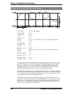
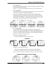
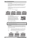
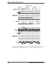
➠ OFFSET DC Offset
This parameter allows you to shift (“offset”) the zero amplitude reference for the
LFO wave. This means that, as depicted in the graphs below, you can move the
zero line – the point of a wave where it is neither positive or negative – up or
down. This is the equivalent of adding a fixed direct current voltage to an
alternating wave.
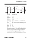
This parameter gives you the ability to add a pitch bend to a vibrato (if the LFO is
modulating an oscillator) or add a volume increase to a tremolo (if the LFO is
modulating a VCA).
Range: -100.00 – +100.00 in increments of .01
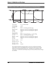
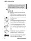
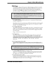
➠ LEVEL Amplitude Select
This is the initial amplitude of the LFO. The term
initial is used because this parameter can be
modulated by another mod source. Therefore,
this parameter sets the LFO’s amplitude before
modulation occurs, if any. If no mod source is
routed to this parameter, its initial level is also its
final level. (Note in the illustration at right that
levels above 50 produce clipping.)
Range: 0 – 100.00 in increments of .01.
Note that the LEVEL of the LFO itself and the LEVEL on a receiver's MOD page are
separate, and interact with each other. Think of this as the "send" and the level
on the oscillator or filter as the "receive".
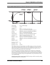
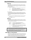
➠ POLAR Polarity
Where the DC Offset parameter (OFFSET, above) allows you to shift the zero
amplitude reference for the LFO wave, this parameter defines which side of zero
the wave will stay on. It simply sets the LFO's polarity – does it produce a positive
voltage, a negative one or both?
BI-POL = center zero: this is a standard “bi-polar” wave – the LFO’s voltage
oscillates both positively and negatively around the zero reference
-POS- = positive: LFO voltage oscillates above the zero reference only
-NEG- = negative: LFO voltage oscillates below the zero reference only