


Chapter 8: Pre Filter, Post Filter and Voice Mixes
ANDROMEDA A6 REFERENCE MANUAL 187
Signal Routing through the Filters
The PRE FILTER MIX outputs of OSC 1 and OSC 2 (along with their respective SUB OSC
signals), the RING MOD and NOISE EXT can be routed through the A6 using the
following procedures.
Please note that the
PRE FILTER MIX output always goes to FILTER 1 unless, of course,
FILTER BYPASS is on. The following procedures will inform you how to turn the
Filters on or off using their respective level knobs, as well as other Filter “mixing”
methods you’ll find useful.
Tip: For these examples, you can experiment with any of the components in PRE
FILTER MIX: the procedures are applicable for any of them or all of them, should
you need to mix in levels of all four knobs.
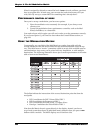
For the component you select, turn its knob to its 2 o’clock position. This will
give you a moderate output level to work with. If you are trying out the VCOs,
you can also mix in their SUB OSCs if you like by turning the knobs clockwise.
Check that the LEVEL knob in VOICE MIX is turned up and adjusted to provide a
comfortable listening level.
Last, turn down all the knobs in POST FILTER MIX as a starting point. The
examples that follow will tell you what knob to use when appropriate.
• To process external audio through FILTER 1 only, turn up the FILT1 LP knob.
This causes
FILTER 1 to output its lowpass-filtered signal. To have the Filter
output other filtered signals – highpass, bandpass or notch – turn up their
respective knobs. (We’ll provide details on these controls under the
Filter
Output Controls
topic on the following page.)
To be certain that you’re only hearing
FILTER 1, make sure that the FILT2 LP
knob is turned fully counter-clockwise. This shuts off the output of FILTER 2.
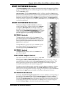
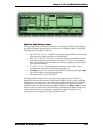
• To process external audio through
FILTER 2 only, press the F2 INPUT button
located on the front panel between the two Filters until the
MIX LED lights.
This routes the output of
PRE FILTER MIX into FILTER 2. Then turn up the FILT2
LP
knob and make sure that all the other knobs in this module are turned
down.
• To process external audio through filters in parallel, use the first two methods
together: when the
MIX function is active, the output of PRE FILTER MIX flows
into
FILTER 2 independently of FILTER 1. Use the FILT2 LP knob to control the
level. And since the output of
PRE FILTER MIX is normally routed to FILTER 1,
use any (or all) of the
FILT1 knobs to mix in the output of FILTER 1.
This functionality of the A6 mixing system provides enormous flexibility: you
can independently mix the levels of two Filters complete with their own
RESONANCE levels, KEY TRACK amounts and modulation. You can even assign
a different envelope to one of the Filters for independent harmonic shaping.
• To process external audio through filters in series, press the
F2 INPUT button
until either the
NOTCH LED lights or the BP (bandpass) LED lights. When
either of these two LEDs are on, that means that the respective output of
FILTER 1 will flow into FILTER 2. Here are the details:
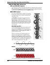
- When using
NOTCH as the input, remember from Chapter 5 that the notch
in the
FILTER 1’s harmonic spectrum is created by using both lowpass and
highpass filtering together (page 118). The input to Filter 2 is post-fader,
meaning that you can turn up the
FILT1 LP and turn down the FILT1 HP knob
which effectively gives you a “
LOWPASS” input instead of NOTCH as it is
labeled on the front panel. Conversely, you can turn down
FILT1 LP and