


Chapter 5: Oscillators and Filters
ANDROMEDA A6 REFERENCE MANUAL 113
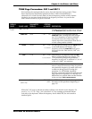
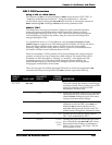
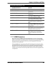
MODULATION DESTINATIONS: VCOs
PARAMETER DISPLAYED AS DEFINITION
1.
FREQUENCY
The frequency of OSC 1 or OSC 2.
2. SQR WAVE LEVEL
The output level of the selected VCO’s
square wave.
3.
PULSE WIDTH
The pulse width of the selected VCO’s
square wave.
4.
OSC2 -> PWM (Oscillator 1 only)
The output of OSC 2 feeding into the
pulse width modulation of
OSC 1 .
5. OSC2 -> LIN FM (Oscillator 1 only)
The output of OSC 2 feeding into the
linear frequency modulation of
OSC 1 .
6. OSC2 -> EXP FM (Oscillator 1 only)
The output of OSC 2 feeding into the
exponential frequency modulation of
OSC 1 .
7.
EXT -> PWIDTH
The output of NZEXT (white, pink, red, or
OSC 1) feeding into the pulse width of the
selected VCO.
8. EXT -> LINFM (Oscillator 1 only)
The output of NZEXT (white, pink, red, or
OSC 1) feeding into the linear frequency
modulation of the selected VCO.
9.
EXT -> EXPFM
The output of NZEXT (white, pink, red, or
OSC 1) feeding into the exponential
frequency modulation of the selected
VCO.
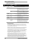
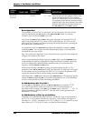
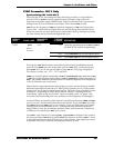
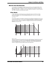
PWMOD/PWM Parameters
Both VCOs provide for PWM or Pulse Width Modulation, shown as PWMOD on the
display. This means that the width setting of the pulse wave set by the
PULSE WIDTH
knob can be varied by a modulation source. This mod has been popular for years and
has been used to re-create many well-known sounds ranging from lush string
ensembles to thick synth pads.
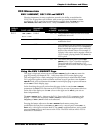
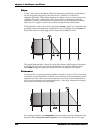
When the
PWM button is pressed on either VCO, the display shows the pulse width
modulation parameters for that VCO. A VCO’s pulse width is most often modulated
by an LFO, but it can easily be modulated by an envelope, the keyboard (velocity,
aftertouch or key track), the pitch bend and modulation wheels, pedals and ribbon
controller, just to name a few of the 79 possible sources in the A6. See Appendix B for
a complete list.