


Chapter 5: Oscillators and Filters
ANDROMEDA A6 REFERENCE MANUAL 111
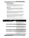
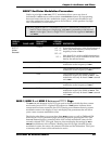
NZEXT Oscillator Modulation Parameters
Similar in principle to OSC 2 FM, NZEXT modulation allows you to use four of
Andromeda’s audio sources and use them as modulation sources. By incorporating
these mod routes into the A6’s modulation system, you now have the ability to use
one of the synthesizer’s three noise sources or Oscillator 1, which produce very high
rates of modulation, as mod sources.
Note that, similar to the ENV1 modulation, the NZEXT modulation parameters for
both VCOs are shown on a single page, with OSC 1's parameters on the left and
OSC 2's on the right. There is a single SOURCE selection that applies to both OSC 1
and OSC 2.
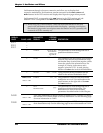
DISPLAY
PAGE PANEL LABEL
PARAMETER
DISPLAY
OPTIONS
or RANGE
DESCRIPTION
NZEXT
Noise/
External
SOURCE
WHT NZ
PNK NZ
RED NZ
OSC 1
Selects the mod source: white (high frequency)
noise, pink (mid frequency) noise, red (low
frequency) noise or
OSC 1.
Note that all five of the available destinations,
described next, can be modulated at the same
time by the selected source.
LINFM1 0 ··· 100
This parameter sets the amount of linear
modulation to the frequency of
OSC 1.
EXPFM1 0 ··· 100
This parameter sets the amount of exponential
modulation to the frequency of
OSC 1.
PWM1
0 ··· 100
This parameter sets the amount of linear
modulation to the Pulse Width of
OSC 1. This
modulation will only be heard if
SQR is turned
on in
OSC 1.
EXPFM2 0 ··· 100
This parameter sets the amount of exponential
modulation to the frequency of
OSC 2.
PWM2 0 ··· 100
This parameter sets the amount of linear
modulation to the Pulse Width of
OSC 2. This
modulation will only be heard if
SQR is turned
on in
OSC 2.
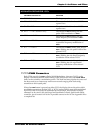
MOD 1, MOD 2 and MOD 3 Buttons and MODS Page
The MOD 1, 2 and 3 buttons in the VCOs are used to display and edit the three custom
mod routes for each VCO. A lighted LED adjacent to a
MOD button indicates that a
custom mod has been created for that VCO. Pressing a mod button shows its current
modulation route in the display (if any) and displays the parameters that will allow
you to create a custom modulation route.
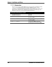
The display also allows you access these three
MODs at once, as well as PWM and FM.
When any of a VCO’s parameter pages are being displayed, pressing the
MODS (soft
button
8) button displays a summary table of the current modulation routes for the
currently selected VCO. (This grid, however, does not display the settings for
ENV 1
AMOUNT
modulation to the oscillators.) Reading from left to right, the table lists the
modulation’s name, the source, the amount, the offset and the destination. This is just
a summary table so none of the soft knobs are active.