


62
Controller Assignments
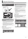
Specifying the Parameter to be Controlled
by the Controller
For each parameter, you can specify, in detail, which controller will
control which parameter.
You can create eight sets of such assignments.
1. In the system parameter PEDAL/GK CTL section, set the
assignment of each controller (CTL, EXP, EXP ON, EXP SW, GK
S1/S2, GK VOL) to “PATCH SETTING.”
For details on how to set system parameters, refer to “Settings for the
Entire GR-55 (SYSTEM)” (p.69).
2. Select the patch whose assignments you want to change
(p.16).
3. In the EDIT screen, choose the MASTER tab and set ASSIGN
1–8 (p.57).
For details on how to set master parameters, refer to “Patch Settings
(MASTER)” (p.54).
4. If you want to keep the settings, save the patch (p.60).
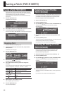
Virtual expression pedal system
(Internal Pedal / Wave Pedal)
By assigning a desired parameter to the virtual expression
pedal, you can produce an eect as though you were
operating a physical expression pedal to change the volume
or tone quality in real time.
The virtual expression pedal system provides the following
two types of functions, and you can use the SOURCE (p.57)
setting for ASSIGN 1–8 to choose the desired type.
* If you want to use the internal pedal or wave pedal, set the
ASSIGN parameter SOURCE MODE to “MOMENT.”
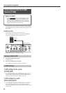
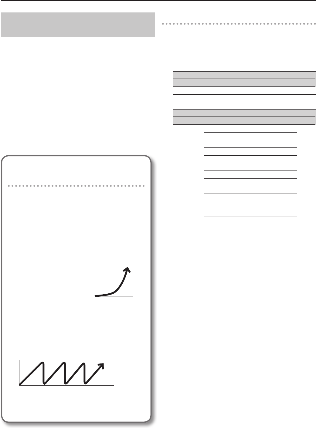
Internal pedal
If SOURCE is set to “INT PDL,” the
virtual expression pedal will begin
operating when started by the
specied trigger (INT TRIG, p.58),
modifying the parameter specied
by TARGET (p.57).
For details on the parameters that
can be assigned to the internal
pedal, refer to “INT TIME” (p.58) and
“INT CURVE” (p.58).
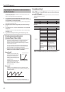
Wave pedal
If SOURCE is set to “WAVE PDL,” the virtual expression pedal
will cyclically modify the parameter specied by TARGET (p.57)
in a xed wave form.
Always changes in a xed curve regardless of the
actual pedal
For details on the parameters that can be assigned to the
wave pedal, refer to “WAVE RATE” (p.58) and “WAVE FORM” (p.58).
The value changes in
a curve
When the trigger occurs
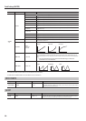
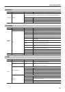
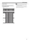
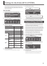
Example setting 1
Make PCM tone 1 smoothly bend up one octave when you
press the [CTL] pedal
Select the patch whose settings you want to edit, and then make the
following parameter settings.
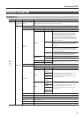
• SYSTEM
PEDAL/GK CTL
Tab Parameter Value Page
CTL FUNCTION PATCH SETTING p.76
• MASTER
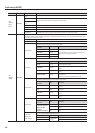
ASSIGN
Tab Parameter Value Page
ASSIGN 1
SWITCH ON
p.57
TARGET PCM1 TONE1 BEND
TARGET MIN 0
TARGET MAX +12
SOURCE INT PDL
SOURCE MODE MOMENT
ACT RANGE LO 0
ACT RANGE HI 127
INT TRIG CTL
INT TIME
20
(Adjust the time over
which the pitch rises an
octave.)
INT CURVE
LINEAR
(You can select a dierent
curve to modify the way in
which the change occurs.)
If you use ASSIGN2 and ASSIGN3 to make the same settings for PCM
TONE 2 and MODELING TONE, you’ll be able to bend up all tones.