


Playing and Editing Programs
46
Detailed Editing with Programs
You can create your own original sounds by edit-
ing the factory Programs, or by initializing a Pro-
gram (Bank E 127: Init. Program
)
and starting from
scratch. You can save these Programs into any
bank other than Bank G or g(d), which cannot be
modified.
Before you begin editing
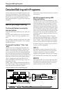
The three attributes of sound: pitch,
tone, and volume
Sound has three basic attributes; pitch, tone, and
volume.
To control these attributes, the microX provides
“oscillator,” “filter,” and “amp (amplifier)” sec-
tions.
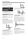
The “oscillator” settings vary the pitch, the “filter”
settings modify the tone, and the “amp” settings
modify the volume.
The microX’s “oscillator,” “filter,” and
“amp”
On the microX, the settings that determine the
“pitch” are located in the PROG 1: Ed–Basic and
PROG 2: Ed–Pitch pages. In the Ed–Basic page
you can specify the waveform (multisample) and
the basic pitch of the waveform. In the Ed–Pitch
page you can specify how the pitch will follow the
keyboard, and make other pitch-related settings.
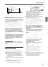
“Filter” settings are made in the PROG 4: Ed–
Filter1 and PROG 5: Ed–Filter2 pages. These set-
tings adjust the tone.
Finally, “Amp” settings are made in the PROG 6:
Ed–Amp1/2 pages. These settings adjust the vol-
ume, and send the sound to the outputs.
These three sections determine the basic sound of
the program.
EG, LFO, keyboard tracking, AMS,
Dmod, controllers
In addition to the sections described above, the
microX provides ways in which the sound can be
varied according to time, key range, or various
types of performance expression. These are con-
trolled by modulators and controllers such as EG
(envelope generator), LFO (Low Frequency Oscil-
lator), keyboard tracking, AMS (Alternate Modu-
lation Source), Dmod (Dynamic modulation) and
the joystick. You can use these modulators and
controllers to apply change to the basic sound of
the program.
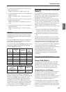
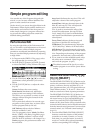
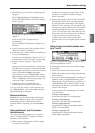
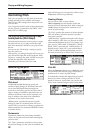
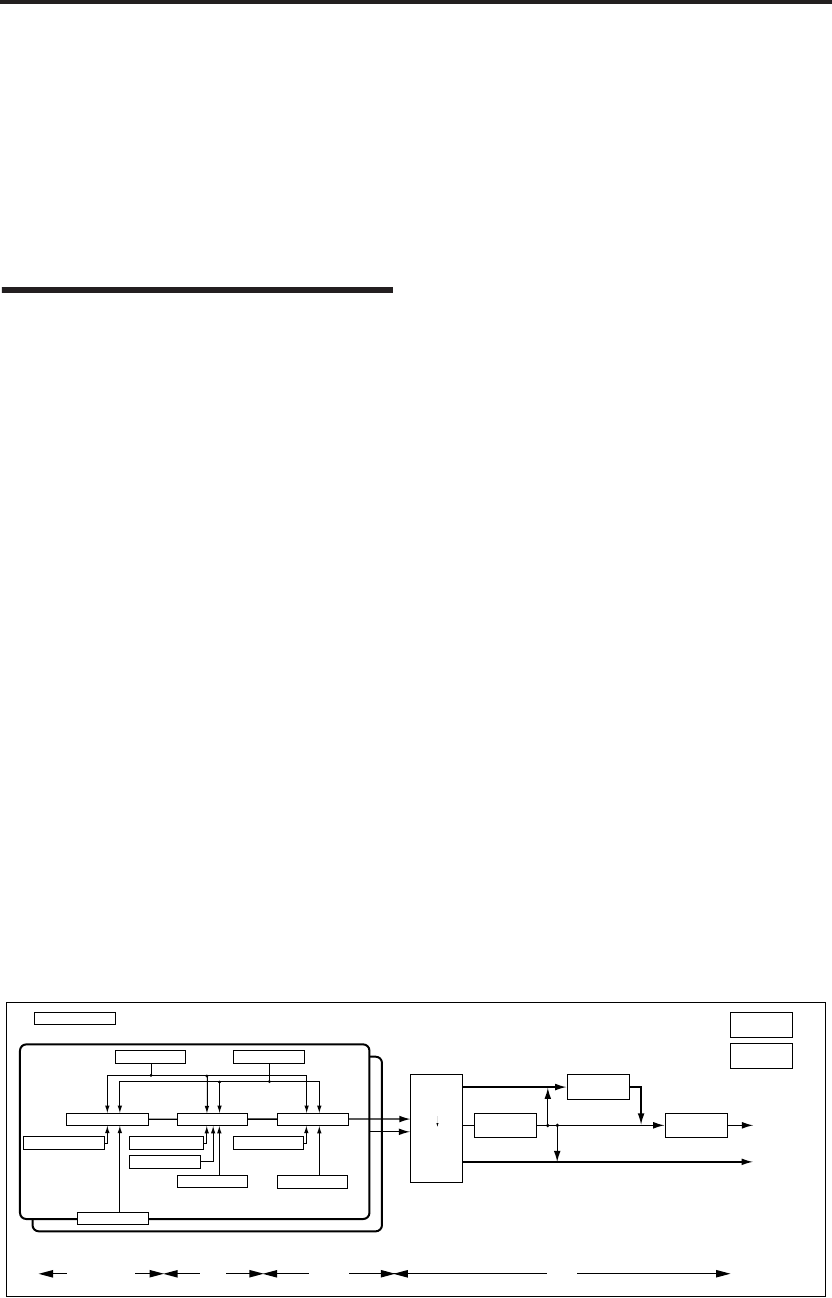
Take a look at the diagram entitled “Program
structure and corresponding pages.” Notice that
the audio signal flows in the order of Oscillator/
Pitch → Filter → Amp. Also notice how modula-
tors such as EG and LFO can affect these blocks.
As shown in figure, a program consists of OSC 1/
2, effects, and the arpeggiator.
OSC 1/2
Each timbre consists of Oscillator/Pitch, Filter,
Amp, EG, and LFO blocks. You can create more
complex programs by using two oscillators
together in one program using the Layer feature.
Note: The Pitch EG is shared by OSC1 and OSC2.
EFFECTS
The output of OSC 1/2 is sent to the insert effect,
the master effects, and the master EQ. The mixer
section lets you control the routing, so you can
specify where the sound will be sent.
OSC 1
OSC 2
AUDIO OUTPUT
L/MONO, R
AUDIO OUTPUT
INDIVIDUAL 1, 2
Oscillator / Pitch
Filter
Amplifier
Effect
OSC1, 2
Insert Effect
Master Effect
Individual-
Output
Insert Effect :
8-1
Oscillator1 Basic : 1-2, 4
Filter1(A/B) : 4-1
Amp1 Level/Pan : 6-1
Pitch EG : 2-5
Filter1 EG : 4-5
Amp1 EG : 6-3
OSC1 LFO1 : 3-1
Filter1 Mod. : 4-2,3
Filter1 LFO Mod. : 4-4
OSC1 Pitch Mod. : 2-1, 2
OSC1 LFO2 : 3-2
Amp1 Mod. : 6-2
Program Basic : 1-1
Insert Effect:
8-2, 3
Master Effect 1, 2:
9-1...3
MasterEQ : 9-4
Controller Setup:
7-3
Arpeggiator :
7-1, 2
Program structure and corresponding pages
1–1, 9–4, etc. indicate the microX on-screen pages and tabs.