


Model 8904A Service
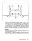
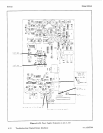
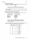
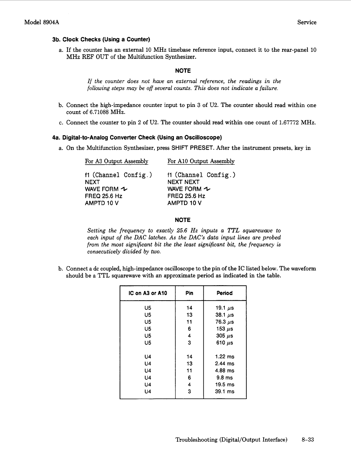
IC
on
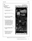
A3
or
A10
u5
u5
u5
u5
u5
u5
u4
u4
u4
u4
u4
u4
3b.
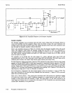
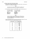
Clock Checks (Using a Counter)
a.
If
the counter has an external 10 MHz timebase reference input, connect
it
to the rear-panel 10
MHz
REF
OUT
of
the Multifunction Synthesizer.
Pin
Period
14 19.1
ps
13 38.1
ps
11 76.3
ps
6 153
ps
4
305
ps
3
610
ps
14 1.22
ms
13 2.44
ms
11 4.88
ms
6 9.8
ms
4 19.5
ms
3
39.1
ms
NOTE
If the counter does not have an external reference, the readings in the
following steps may be
off
several counts. This does not indicate a failure.
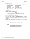
b. Connect the high-impedance counter input to pin
3
of
U2.
The counter should read within one
c. Connect the counter to pin
2
of
U2.
The counter should read within one count of 1.67772 MHz.
count of 6.71088 MHz.
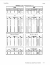
4a.
Digital-to-Analog Converter Check (Using an Oscilloscope)
a. On the Multifunction Synthesizer, press
SHIFT
PRESET.
After the instrument presets, key in
For
A3
Output Assembly
fl
(Channel Config.)
NEXT NEXT NEXT
WAVE
FORM
(t
FREQ
25.6
Hz
AMPTD
10
V
For
A10 Output Assembly
fl
(Channel Config.)
WAVE
FORM
(t
FREQ
25.6
Hz
AMPTD
10
V
NOTE
Setting the frequency to exactly
25.6
Hz
inputs a
TTL
squarewave to
each input of the DAC latches. As the DAC’s data input lines are probed
from the most significant bit the the least significant bit, the frequency
is
consecutively divided
by
two.
b. Connect a dc coupled, high-impedance oscilloscope to the pin of the
IC
listed below. The waveform
should be a TTL squarewave with an approximate period as indicated in the table.
Troubleshooting (Digital/Output Interface)
8-33