


Service Model 8904A
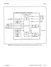
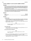
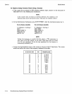
A2 DIGITAL ASSEMBLY
TO
A3
(OR
A10)
OUTPUT
ASSEMBLY INTERFACE
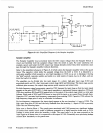
Description
The following procedure will help identify whether an instrument failure is due to the analog output
circuits
or
their control inputs. Since the layout of the instrument board assemblies breaks the circuit
assemblies along digital-analog lines, this procedure will also help determine which assembly (the
A2
Digital Assembly
or
the A3
(or
A10) Output Assembly)
is
at
fault.
It
does this by checking signals on
the interface between the
two
assemblies.
If the tests pass but the output
is
faulty, the A3
(or
A10) assembly should be replaced.
If
the tests fail,
trace the signal to the A2 assembly. Retest the line that was faulty to determine whether the fault
is
in
A2
or
its
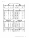
interconnection to A3. Refer to Table
8-2,
A3 and A10 Interconnections to A2,
at the end
of
this procedure for a cross reference of the signal interconnections.
Equipment
Counter
..........................................................................
HP 5315B
Digital Multimeter
................................................................
HP 3478A
Oscilloscope
.....................................................
HP 1740A
or
Tektronix 2235
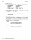
Procedure
1.
Preliminary Setup
a.
If
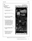
the instrument has Option 002 (a second output assembly, A10) and Output
1
(the output from
the A3 Output Assembly)
is
to be checked, move the A10 Output Assembly out of the way. (Refer
to Figure 8-11,
How to Access A3 in Instruments Equipped with Option
002.)
b. Check that switches
1
and
2
of the Service Switch, S1, on the
A2
Digital Assembly are open and
switches 3 through 10 are closed.
NOTE
The reference designators called out in the procedures are for the A3 or
A1
0
Output Assembly.
2.
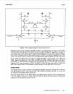
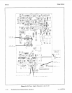
Power Supply Checks
Connect a voltmeter to the points shown in Figure 8-12,
Power Supply Testpoints on A3
or
AlO.
The readings should be very close to those indicated.
3a. Clock Checks (Using an Oscilloscope)
NOTE
This procedure is adequate for most
cases.
Step 3b (which uses a counter),
however, is more exact.
a.
Connect a dc coupled, high-impedance oscilloscope to pin 3 of U2. The waveform should be
a
b. Connect the oscilloscope to pin
2
of U2. The waveform should be a TTL squarewave with a period
TTL
squarewave with
a
period of approximately 150 ns (a frequency of 6.7 MHz).
of
approximately 600 ns (a frequency of 1.68 MHz).
8-30 Troubleshooting (Digital/Output Interface)