


Instrument Changes Model 8904A
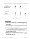
Removing the Front
Panel
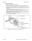
3. Unplug the
two
connectors
on
the top front edge of the A2 Digital Assembly that are attached
to the
A5
LCD Display. (Refer to figure 6-3. The
two
cables are labeled as P/O A5.)
4.
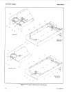
Remove the top trim strip (item 67 in figure 6-5) and
two
side strips (items 61 and 62) from the
front-panel frame.
5.
Remove the 10 screws (items 75 through 84 in figure 6-1, 2712A to 2917A) that secure the
front-panel assembly to the front frame (item 89).
6. Pull the front panel part way out until
it
is easy to access AlW1. (Refer to figure 6-1. AlWl is
the remaining wide ribbon cable at the front of the A2 Digital Assembly.) Unplug the cable from
the
A2
assembly.
7. Pull the front panel further out to reveal the
two
T-8
Torx screws with lockwashers (items 73
and
74
in figure 6-1) securing the line switch to the bottom of the front panel then remove the
two screws. (The screws will not be reused.)
8.
Remove the front-panel
BNC
connectors from the front panel. (There may be four,
two,
or
no
connectors depending on the presence of Option
002
and Option 004.) Be sure to identify which
cable goes in which hole.
(A
simple identification scheme
is
to put the nut back on the connectors
for the
“HIGH”
outputs only.) The front panel should now be free
of
the instrument.
9. Remove the
“LINE”
keycap from the line switch. The switch’s stem is easily snapped
or
pulled
out of the switch’s body. When removing the keycap, do not allow the stem to flex and do not
hold the body of the switch. Pull the keycap straight out.
10. Press the new, unlabeled keycap
(HP
0371-3802) on the line switch.
Transferring the
A5
LCD
Display
11.
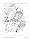
Remove the four Torx screws with lockwashers (items 44, 45, 49, and 51 in figure 6-3) securing
the old display shield (item 39) to the old front panel and remove the display shield.
12. Remove the four Torx screws with lockwashers (items
40
through 43 in figure 6-3) securing the
A5 LCD Display to the old front panel and remove the display. (The screws will not be reused.)
13. Remove the four Torx screws and captive lockwashers securing the new display shield to the new
front panel and temporarily remove the new display shield.
14. Install the LCD display on to the new front panel securing
it
with the four new screws and
captive lockwashers
(HP
0515-1851) from the kit. Tighten the screws to 0.6 N.m (5 inelb).
15. Re-install the new display shield on to the new keyboard with the four screws and captive
lockwashers removed in step 13. Alignment of the shield
is
critical. The shield should be pulled
up as high as the screw slots will allow. Tighten the screws to
1.1
N.m
(9
in.lb).
7-16 Firmware Updates/Hardware Modifications
rev.
15DEC89