


Instrument Changes Model 8904A
Cable
Routing
1.
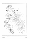
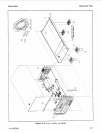
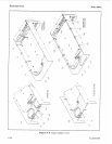
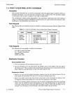
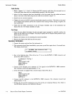
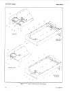
Refer to figures 7-1, 7-2 and 7-3. Remove the BNC connector ends from the front panel one at
2.
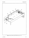
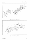
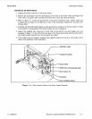
After all of the connectors have been transferred to the rear panel, secure the cables to the side
3.
Install one new lock washer and one new nut on each connector.
4. Tighten the nuts on the BNC connectors hand tight using the nut driver. (The holes in the panel
are
D
shaped and therefore prevent the connector from turning without having to tighten the
nuts excessively.)
5. Verify that the
SMC
connections on the
A3
Output Assembly and,
if
the instrument has
Option
002,
the A10 Output Assembly are tight.
a time and insert them into the corresponding openings in the rear panel.
rail as shown in figure 7-3 using the new cable ties.
Final Steps
1.
Insert the new plastic hole-plugs into the front-panel output openings by carefully working the
plugs into the holes with your fingers. The plugs
fit
tightly and will require some pressure to get
them started in the holes.
2.
Replace the bottom cover by reversing the removal procedure.
3.
Type or write the date and option number on the new blank label in the following form:
day/month/year
:
Opt
.
004.
Peel
off
the protective backing and stick the label
on
the rear
panel.
(Do
not place the label over the existing serial number tag.)
Operation Verification
1.
Connect the power cord and turn the instrument on.
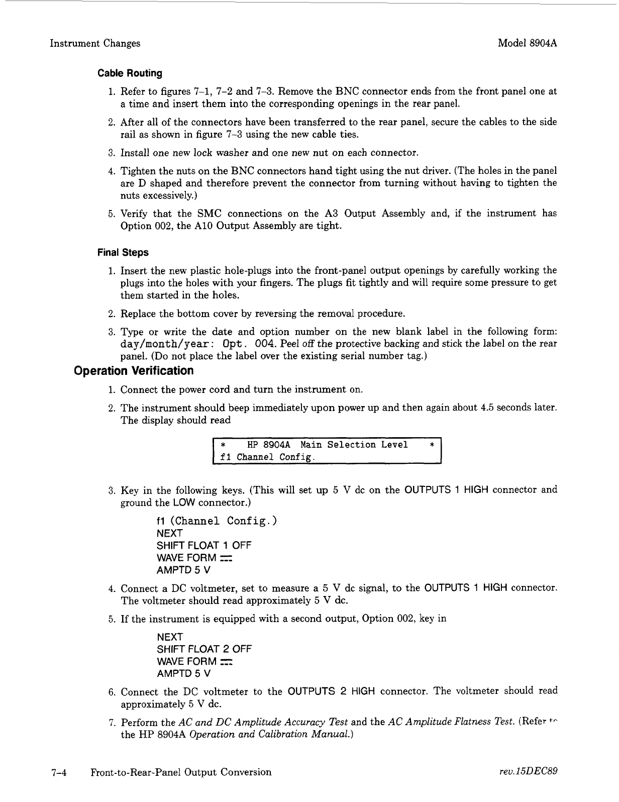
2.
The instrument should beep immediately upon power up and then again about 4.5 seconds later.
The display should read
*I
*
HP
8904A Main Selection Level
I
fl
Channel Confie.
3.
Key in the following keys. (This will set up
5
V
dc on the
OUTPUTS
1
HIGH
connector and
ground the
LOW
connector.)
fl
(Channel Conf
ig.
)
NEXT
SHIFT FLOAT
1
OFF
WAVE FORM
=
AMPTD
5
V
4.
Connect a DC voltmeter, set to measure a
5
V
dc signal, to the
OUTPUTS
1
HIGH
connector.
5. If the instrument is equipped with a second output, Option 002, key in
The voltmeter should read approximately
5
V
dc.
NEXT
SHIFT FLOAT
2
OFF
WAVE FORM
5=1
AMPTD
5
V
6.
Connect the DC voltmeter to the
OUTPUTS
2
HIGH
connector. The voltmeter should read
7.
Perform the
AC and
DC
Amplitude Accuracy
Test
and the
AC Amplitude Flatness Test.
(Refer
+,.
approximately 5 V dc.
the HP 8904A
Operation and Calibration Manual.)
7-4 Front-to-Rear-Panel Output Conversion
rev. 15DEC89