


Service Model 8904A
+15V +15v
&
R213
I
II
c201
11
DAC-ANLSA’LIPLER
r
-1
R216
;+(f\;
I
I I
iz
L----I
+
TO
DAC-ANLSA’LIPLER
r
-1
R216
tTHlS
LINE
IS
AT GUARD
TRACE POTENTIAL
LOW-PASS
FILTER
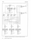
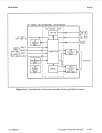
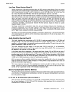
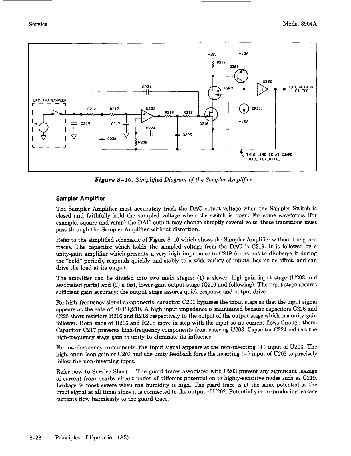
Figure
8-10.
Simplified Diagram
of
the Sampler Amplifier
Sampler Amplifier
The Sampler Amplifier must accurately track the DAC output voltage when the Sampler Switch is
closed and faithfully hold the sampled voltage when the switch
is
open.
For
some waveforms (for
example, square and ramp) the DAC output may change abruptly several volts; these transitions must
pass through the Sampler Amplifier without distortion.
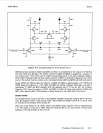
Refer
to
the simplified schematic of Figure
8-10
which shows the Sampler Amplifier without the guard
traces. The capacitor which holds the sampled voltage from the DAC
is
C219.
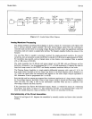
It
is followed by a
unity-gain amplifier which presents
a
very ‘high impedance
to
C219
(so
as
not to discharge it during
the “hold” period), responds quickly and stably to
a
wide variety of inputs, has no dc offset, and can
drive the load at
its
output.
The amplifier can be divided into
two
main stages:
(1)
a slower, high-gain input stage (U203 and
associated parts) and
(2)
a fast, lower-gain output stage (Q210 and following). The input stage assures
sufficient gain accuracy; the output stage assures quick response and output drive.
For
high-frequency signal components, capacitor C201 bypasses the input stage
so
that the input signal
appears
at
the gate of FET Q210. A high input impedance is maintained because capacitors C226 and
C225 short resistors R216 and R218 respectively to the output
of
the output stage which is a unity-gain
follower. Both ends of R216 and
R218
move in step with the input
so
no current flows through them.
Capacitor C2 17 prevents high-frequency components from entering U203. Capacitor C224 reduces the
high-frequency stage gain to unity
to
eliminate
its
influence.
For
low-frequency components, the input signal appears at the non-inverting
(+)
input of U203. The
high, open-loop gain
of
U203 and
the
unity feedback force the inverting
(->
input of U203 to precisely
follow the non-inverting input.
Refer now to Service Sheet
1.
The guard traces associated with U203 prevent
any
significant leakage
of
current from nearby circuit
nodes
of different potential on
to
highly-sensitive nodes such as C219.
Leakage
is
most severe when the humidity
is
high. The guard trace
is
at the same potential as the
input signal at all times since
it
is connected to the output
of
U202. Potentially error-producing leakage
currents flow harmlessly to the guard trace.
8-26 Principles of Operation (A3)