


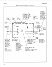

Service Model
8904A
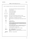
Table
8-1.
Schematic Diagram Notes
(3
of
11)
-L
4
,,
J.
,,
1
,,
322
'I
Y
-
T
4
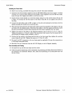
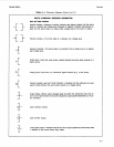
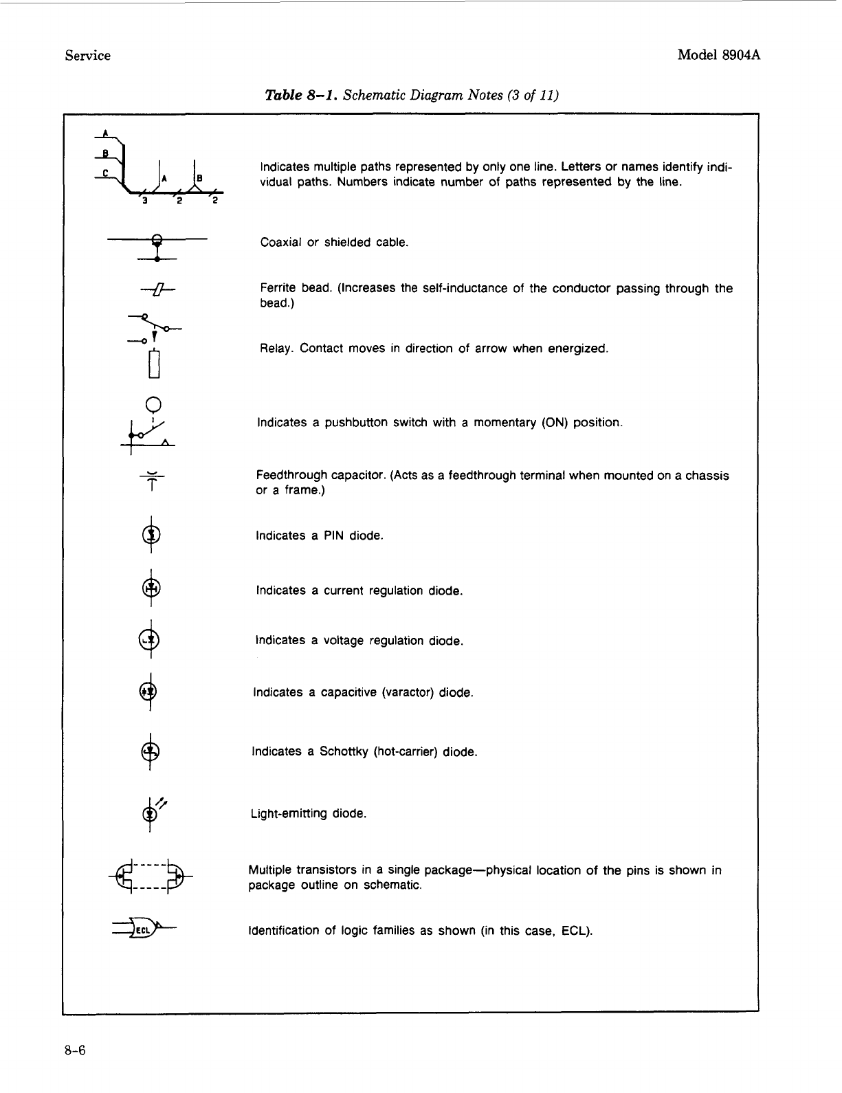
Indicates multiple paths represented by only one line. Letters or names identify indi-
vidual paths. Numbers indicate number
of
paths represented by the line.
Coaxial or shielded cable.
Ferrite bead. (Increases the self-inductance of the conductor passing through the
bead.)
Relay. Contact moves in direction
of
arrow when energized.
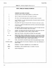
Indicates a pushbutton switch with a momentary
(ON)
position.
Feedthrough capacitor. (Acts as a feedthrough terminal when mounted on a chassis
or a frame.)
Indicates a PIN diode.
Indicates a current regulation diode.
Indicates a voltage regulation diode.
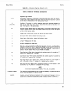
Indicates a capacitive (varactor) diode.
Indicates a Schottky (hot-carrier) diode.
Light-emitting diode.
Multiple transistors in a single package-physical location
of
the pins is shown in
package outline on schematic.
Identification of logic families as shown (in this case,
ECL).
8-6