


Model 8904A Service
PHASE SYNCHRONIZATION (OPTION
005)
Description
The operation of the unit-to-unit phase synchronization circuits (Option
005
and serial prefix
beginning 2948A only) is checked by monitoring the signals on the rear-panel clock synchronization
and phase reset input and output lines. The checks should pinpoint the failure to either the
A2
Digital
Assembly
or
an interconnecting cable. Marginal failures may be able to be corrected by performing
the
Phase Synchronization Adjustment
in Section
5;
however, this is recommended only when there
is strong reason to suspect that the failure is due to slight timing errors. Performance
of
the phase
synchronization circuits can be verified by running the
Unit-to- Unit Phase Accuracy Performance Test
in Section 4.
Equipment
Digital Multimeter
................................................................
HP 3478A
Oscilloscope
.....................................................
HP 1740A
or
Tektronix 2235
Procedure
1.
2.
3.
4.
5.
6.
7.
8.
9.
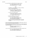
On the Multifunction Synthesizer, connect the rear-panel
CLOCK SYNC OUTPUT
to the
oscilloscope input. Set the oscilloscope’s input to
500
or
terminate the input in
50R
using a tee.
On the Multifunction Synthesizer, press
SHIFT PRESET.
After the instrument presets, key in
SHIFT
SPECIAL
7
ENTER
f2
(Status)
ON
LAST
f2
(Status)
ON
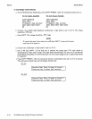
The oscilloscope should show a
TTL
waveform with a period of 74.5 ns (a frequency of 13.4
MHz).
If
faulty, check the cable which terminates at A2J9.
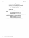
Connect the oscilloscope to A2TP1. (The oscilloscope input should remain
at
50R.)
Connect a
short
BNC
cable between the rear-panel
CLOCK SYNC OUTPUT
and
CLOCK SYNC INPUT.
The oscilloscope display should be the same as in step 3.
If
faulty, check the cable which
terminates at A2J10.
Connect the oscilloscope input
or
a logic probe to the rear-panel
9
RESET
OUTPUT.
If an
oscilloscope
is
used, set it to single trigger. On the Multifunction Synthesizer, press
f4
(Exit).
Key in
SHIFT
iP
RESET
several times and observe the oscilloscope
or
the logic probe. The logic
probe should blink a high each time. The oscilloscope should trigger a sweep each time. (It may
be necessary to adjust the oscilloscope’s trigger level and the trigger may need to be armed each
time.)
If
faulty, check the cable which terminates at
A2Jll.
Connect a short
BNC
cable between the rear-panel
Q,
RESET OUTPUT
and
@
RESET INPUT.
Connect the oscilloscope input
or
a logic probe
to
A2U30 pin
12.
Key in
SHIFT
iP
RESET
several times, as was done in step
6,
and observe the oscilloscope
or
the logic probe. The logic probe should blink a high each time. The oscilloscope should trigger a
sweep each time.
If
faulty, check the cable which terminates at A2J12.
rev.
15DEC89
Troubleshooting (Phase Synchronization)
8-42.1