


Model
8904A
Service
A3
OR
A10
OUTPUT
ASSEMBLY
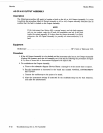
Description
The following procedure will
assist
in locating a fault on the A3 or A10 Output Assembly.
It
is
wise
to
perform the procedure titled
A2
Digital Assembly to
A3
(or
A10) Output Assembly Interface
first to
confirm that the fault is indeed on the Output Assembly.
NOTE
If
the instrument has Option
002,
a second output, and the fault appears
only on one output, swap the
A3
and
A10
assemblies and see
if
the fault
tracks the output assembly. If
it
does, then the Output Assembly
is
at
fault;
otherwise, the A2 Digital Assembly
(or
possibly an interconnection)
is
at
fault.
Equipment
Oscilloscope
.
.
. . . .
.
. .
. .
. .
.
.
. . .
. . .
.
. . .
.
. . . .
.
.
.
. . . .
.
.
. .
.
. .
.
. .
.
.
. .
. . HP
1740A
or Tektronix
2235
Procedure
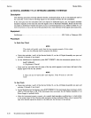
1.
If
the A3 Output Assembly is to be checked and the instrument
also
has
an
A10 Output Assembly
(Option
002)
present, move the
A10
assembly out of the way by following the procedure of Figure
8-11,
How to Access
A3
in
Instruments Equipped with Option
002.
2.
To troubleshoot the Output Assembly,
a.
Turn
to the schematic diagram (Service Sheets
1
through
4)
of the circuit that
is
suspect.
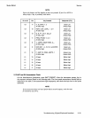
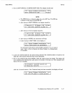
b. Set the instrument
as
instructed in the boxed text entitled “INITIAL INSTRUMENT
SETTINGS”.
c. Connect the oscilloscope
to
the point to be tested.
d. Alter the instrument settings if instructed by the troubleshooting text for that testpoint,
and make the measurement.
8-42
Troubleshooting (A3
or
A10 Assembly)