


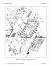
Model
8904A
llzble
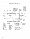
8-1.
Schematic Diagram Notes
(4
of
11)
Service
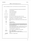
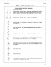
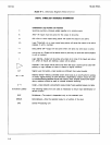
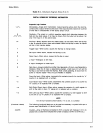
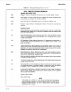
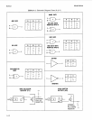
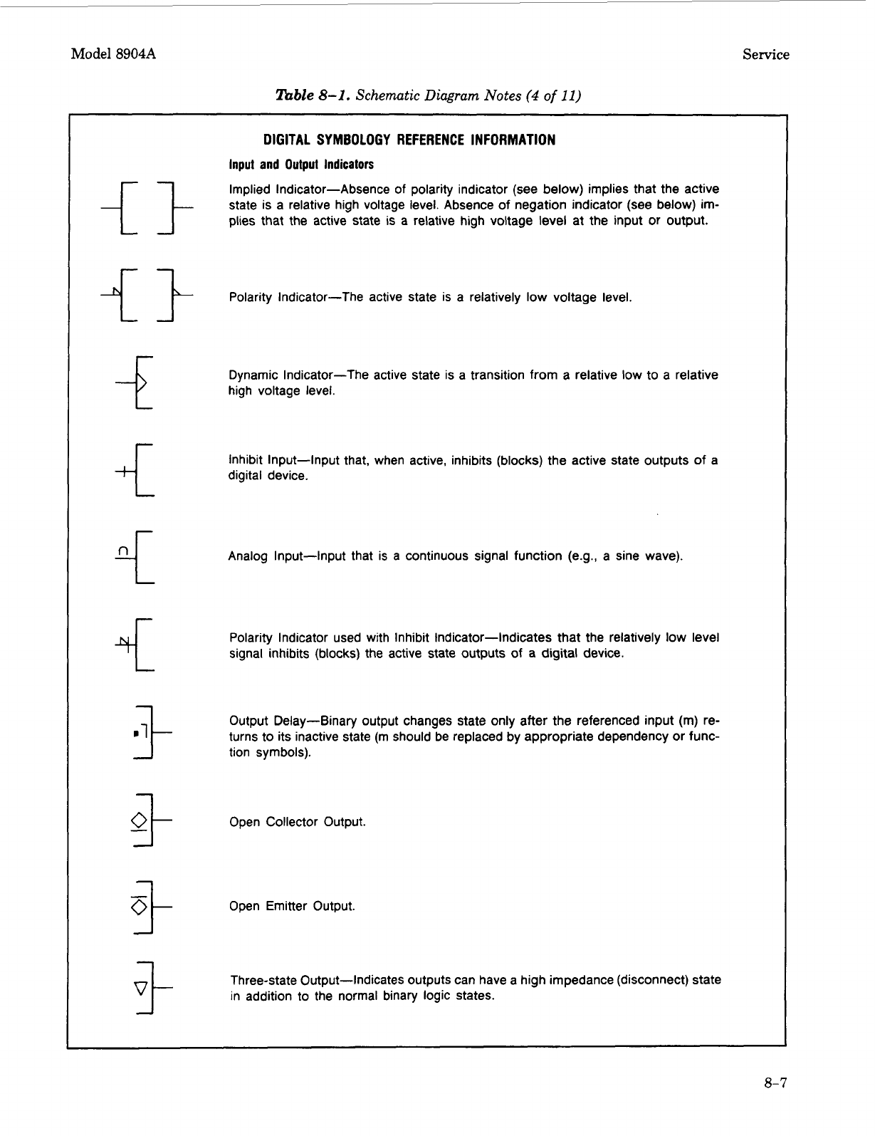
DIGITAL SYMBOLOGY REFERENCE INFORMATION
Input and Output Indicators
Implied Indicator-Absence of polarity indicator (see below) implies that the active
state is a relative high voltage level. Absence
of
negation indicator (see below) im-
plies that the active state is a relative high voltage level at the input
or
output.
Polarity Indicator-The active state
is
a relatively low voltage level.
Dynamic Indicator-The active state is a transition from a relative low to a relative
high voltage level.
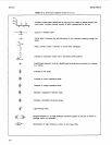
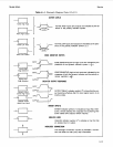
Inhibit Input-Input that, when active, inhibits (blocks) the active state outputs
of
a
digital device.
Analog Input-Input that
is
a continuous signal function (e.g., a sine wave).
Polarity Indicator used with Inhibit Indicator-Indicates that the relatively low level
signal inhibits (blocks) the active state outputs of a digital device.
Output Delay-Binary output changes state only after the referenced input (m) re-
turns to its inactive state
(m
should be replaced by appropriate dependency
or
func-
tion symbols).
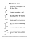
Open Collector Output.
Open Emitter Output.
Three-state Output-Indicates outputs can have a high impedance (disconnect) state
in addition to the normal binary logic states.
8-7