


Service Model 8904A
A3
OUTPUT ASSEMBLY (Service Sheets
1
through
4)
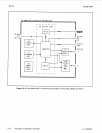
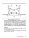
General
The A3 Output Assembly converts the digitally encoded waveform from the digital waveform synthesis
integrated circuit (DWSIC) on the A2 Digital Assembly to a precise
and
useable analog signal.
Instruments with Option 002 have a second Output Assembly (designated A10) which
is
identical
to A3.
For
troubleshooting purposes the
two
Output Assemblies can be interchanged
or
compared
node-for-node. Specifically, the Output Assembly contains:
0
the digital-to-analog converter
0
a track-and-hold circuit
0
clean up filters
0
amplifiers and attenuators
0
reverse power protection
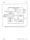
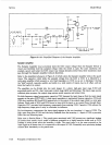
Digital-to-Analog Converter (Service Sheet
1)
IC U6 is a 12 bit Digital-to-Analog Converter (DAC).
Its
function
is
to generate current with a
magnitude proportional to the weighted 12 bit input data from DWSIC via latches U4
and
U5. New
data
is
output to the latches at a 1.6777216
MHz
clock rate. The latches hold the
data
until
it
is time to
clock the data to the DAC. Clocking of the latches
is
delayed 60 ns by U16 for optimum synchronization
of the DAC and the following Track-and-Hold Circuit.
The output of the DAC is converted to a voltage by the series combination of resistors R210, R224,
and R221. R224 (DAC Level) is adjusted to give the correct waveform amplitude. Connector 54 is a
convenient point for testing the DAC when jumper 5201
is
moved to connect point 2 to point 3.
Track-and-Hold Circuit (Service Sheet
1)
After data is placed on the input of the DAC, the DAC requires
300
ns (that is, one-half clock period)
settling before
its
output is valid. The Track-and-Hold circuit following the DAC stores (holds) the
DAC’s previous valid output on a capacitor (C219 at the input of the Sampler Amplifier) for 300 ns
while the DAC with its new input data settles. Then the DAC’s output
is
sampled
and
tracked for
300
ns.
The Track-and-Hold Circuit can be divided into three parts:
0
Sampler Drive
0
Sampler Switch
0
Sampler Amplifier
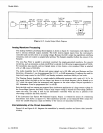
Sampler
Drive
The Sampler Drive must provide sufficient current through transformer
T1
to turn on hard the sampler
diodes (U201A,
B,
C, and
F)
in the Sampler Switch. When the sampler diodes are on, the voltage at
the DAC output transfers to capacitor C219 at the input of the Sampler Amplifier. Operation of the
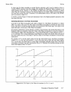
Sampler Drive is most easily seen by referring to the simplified schematic of Figure 8-9.
8-24
Principles of Operation (A3)