


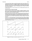

Service Model 8904A
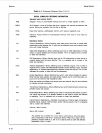
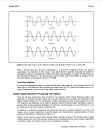
P=3
is
an interesting case. The count sequence (in decimal) is
0,
3,
6,
9,
12,
15,
2,
5,
8,
11, 14, 1,
4,
7,
10, 13,
0,
etc. The Latch outputs three uneven staircases that repeat every
16
clock periods.
In general, if
P
is
not
0
but is small compared to the number of possible states
(16
in the current
example), the Latch outputs a series of staircases (sometimes uneven) with a frequency equal to the
Clock frequency
x
P
+
16.
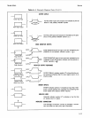
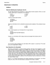
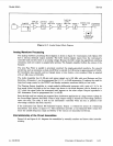
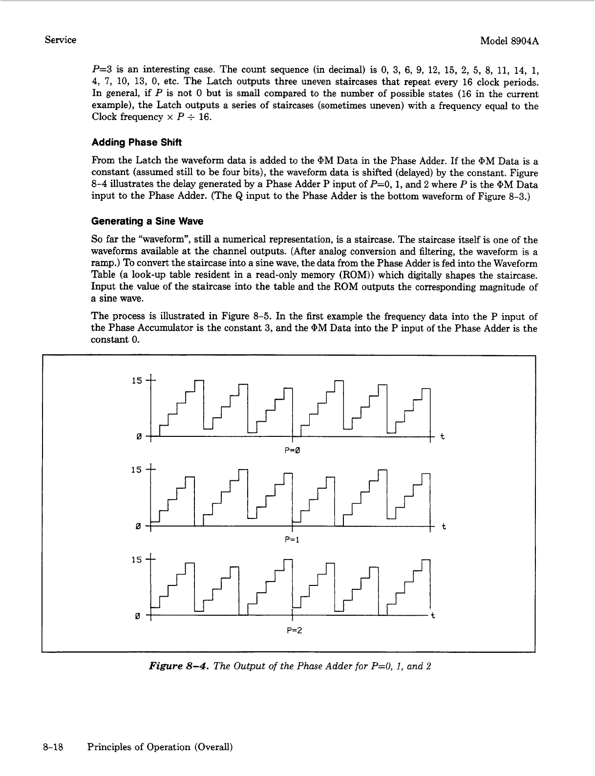
Adding Phase Shift
F’rom the Latch the waveform
data
is
added
to
the
@M
Data in the Phase Adder.
If
the
@M
Data
is
a
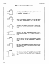
constant (assumed still to be four bits), the waveform data is shifted (delayed) by the constant. Figure
8-4
illustrates the delay generated by
a
Phase Adder
P
input of
P=O,
1,
and
2
where
P
is the @M Data
input to the Phase Adder. (The
Q
input to the Phase Adder
is
the bottom waveform of Figure
8-3.)
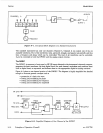
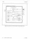
Generating a Sine Wave
So
far the “waveform”, still a numerical representation,
is
a staircase. The staircase itself
is
one of the
waveforms available at the channel outputs.
(After
analog conversion and filtering, the waveform is a
ramp.) To convert the staircase into a sine wave, the
data
from the Phase Adder
is
fed into the Waveform
Table (a look-up table resident in a read-only memory (ROM)) which digitally shapes the staircase.
Input the value of the staircase into the table and the ROM outputs the corresponding magnitude of
a sine wave.
The process
is
illustrated in Figure
8-5.
In the first example the frequency data into the P input of
the Phase Accumulator
is
the constant
3,
and the
@M
Data into the
P
input
of
the Phase Adder is the
constant
0.
t
P=O
15
0
P=
1
t
P=2
Figure
8-4.
The Output
of
the Phase Adder
for
P=O,
1,
and
2
8-18 Principles of Operation (Overall)