


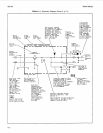
Service Model
8904A
Table
8-1.
Schematic Diagram Notes
(7 of
11)
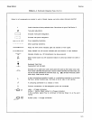
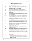
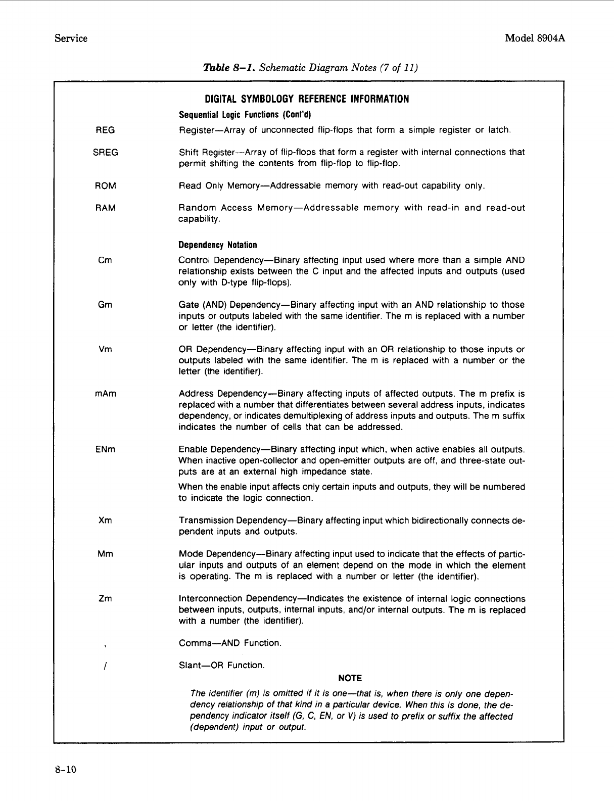
DIGITAL SYMBOLOGY
REFERENCE
INFORMATION
Sequential
Logic
Functions (Cont’d)
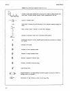
Register-Array of unconnected flip-flops that form a simple register or latch.
Shift Register-Array of flip-flops that form a register with internal connections that
permit shifting the contents from flip-flop
to
flip-flop.
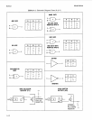
REG
SREG
ROM
RAM
Crn
Gm
Vm
mAm
ENm
Xm
Mm
Zm
I
Read Only Memory-Addressable memory with read-out capability only.
Random Access Memory-Addressable memory with read-in and read-out
capability.
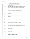
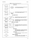
Dependency Notation
Control Dependency-Binary affecting input used where more than a simple AND
relationship exists between the
C
input and the affected inputs and outputs (used
only with D-type flip-flops).
Gate (AND) Dependency-Binary affecting input with an AND relationship to those
inputs or outputs labeled with the same identifier. The m is replaced with a number
or letter (the identifier).
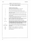
OR
Dependency-Binary affecting input with an
OR
relationship
to
those inputs or
outputs labeled with the same identifier. The m is replaced with a number or the
letter (the identifier).
Address Dependency-Binary affecting inputs of affected outputs. The m prefix is
replaced with a number that differentiates between several address inputs, indicates
dependency, or indicates demultiplexing of address inputs and outputs. The m suffix
indicates the number of cells that can be addressed.
Enable Dependency-Binary affecting input which, when active enables all outputs.
When inactive open-collector and open-emitter outputs are
off,
and three-state out-
puts are at an external high impedance state.
When the enable input affects only certain inputs and outputs, they will be numbered
to indicate the logic connection.
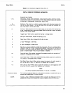
Transmission Dependency-Binary affecting input which bidirectionally connects de-
pendent inputs and outputs.
Mode Dependency-Binary affecting input used to indicate that the effects of partic-
ular inputs and outputs of an element depend on the mode in which the element
is operating. The m is replaced with a number or letter (the identifier).
Interconnection Dependency-Indicates the existence of internal logic connections
between inputs, outputs, internal inputs, and/or internal outputs. The m is replaced
with a number (the identifier).
Comma-AND Function.
Slant-OR Function.
NOTE
The identifier (m) is omitred
if
it is one-that is, when there is only one depen-
dency relationship of rhat kind in a particular device. When this is done, the
de-
pendency indicator itself
(G,
C,
EN,
or
V)
is used to prefix or suffix the affected
(dependent) input or output.
5-10