


Model
8904A
5.
Miscellaneous Control Checks
Service
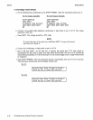
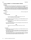
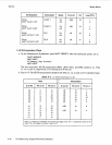
a. On the Multifunction Synthesizer, press
SHIFT PRESET.
After the instrument presets, key in
For
A3
Output Assembly
For
A10
Output Assembly
fl
(Channel Config.)
NEXT NEXT NEXT
fl
(Channel
Config.
)
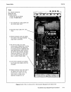
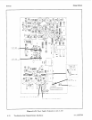
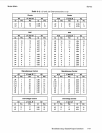
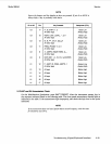
b. Connect a dc coupled, high-impedance oscilloscope
or
logic probe to the pin
of
the
IC
listed in
the table below.
For
each connection, key in the sequences listed in the table (in the order listed)
and note the logic state.
Function
Filter
24
dB
Attenuator
12
dB
Attenuator
6
dB
Attenuator
On/Off Switch
48
dB
Attenuator
Float/Ground Switch
A3 Key Sequence
SHIFT
FILTER
1
fl
fl
(Filter Select)
AMPTD
1OV
625
rnV
1
ov
2.5V
1
ov
5v
SHIFT
OUTPUT
1
ON
SHIFT
OUTPUT
1
OFF
AMPTD
1OV
39
rnV
SHIFT
FLOAT
1
ON
SHIFT
FLOAT
1
OFF
~
A10 Key Sequence
SHIFT
FILTER
2
fl
fl
(Filter Select)
AMPTD
1OV
625
rnV
1
ov
2.5V
1
ov
5v
SHIFT
OUTPUT
2
ON
SHIFT
OUTPUT
2
OFF
AMPTD
10
V
39
rnV
SHIFT
FLOAT
2
ON
SHIFT
FLOAT
2
OFF
A3/A10 Connection
IC
U8
u10
u10
u10
U8
U8
U8
Pin
1
1
3
5
6
3
7
-
TTL
Level
-
L
H
H
L
H
L
H
L
L
H
H
L
L
H
-
Troubleshooting (Digital/Output Interface)
8-35