


Modei 8904A Service
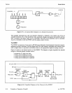
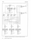
In many ways the figure resembles an analog function generator, and
it
may be helpful at times to
visualize DWSIC operation using this analogy. (For example, the Waveform Table
is
analogous to an
analog shaping circuit.) However, in the DWSIC all signal lines carry signal information as binary
codes. Thus, the “waveforms” shown in the following figures are not really voltage-versus-time plots but
are coded-value-versus-time plots. Conversion to an analog signal occurs at the output
of
the DWSIC
and is not shown in Figure 8-2.
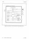
It should be noted in Figure 8-2 that each interconnect line in the diagram generally represents a data
bus several bits wide.
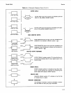
Generating Staircases in the Phase Accumulator
Look first at the Phase Accumulator and Latch in Figure 8-2. The Phase Accumulator is a binary
adder-its output is the
sum
P+Q. The output of the Phase Accumulator
is
the
data
(D) input
of
the
Latch. This input is clocked through the latch once each period of the Clock input. The output of the
latch feeds back to the
Q
input
of
the Phase Accumulator.
For purposes
of
illustration, assume all data is carried on four-bit buses. Also assume that inputs to the
Frequency Adder are constants
so
that the
P
input of the Phase Accumulator
is
a four-bit constant
P.
(The Frequency Adder will be discussed later.)
P
can theoretically take on values between
0
and
24-1
or
15
(in decimal). This constant represents a fixed frequency
as
will be seen shortly. Each clock period
the Latch outputs the sum
of
the input
P
and the output of the Phase Accumulator
of
the previous
clock period.
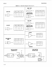
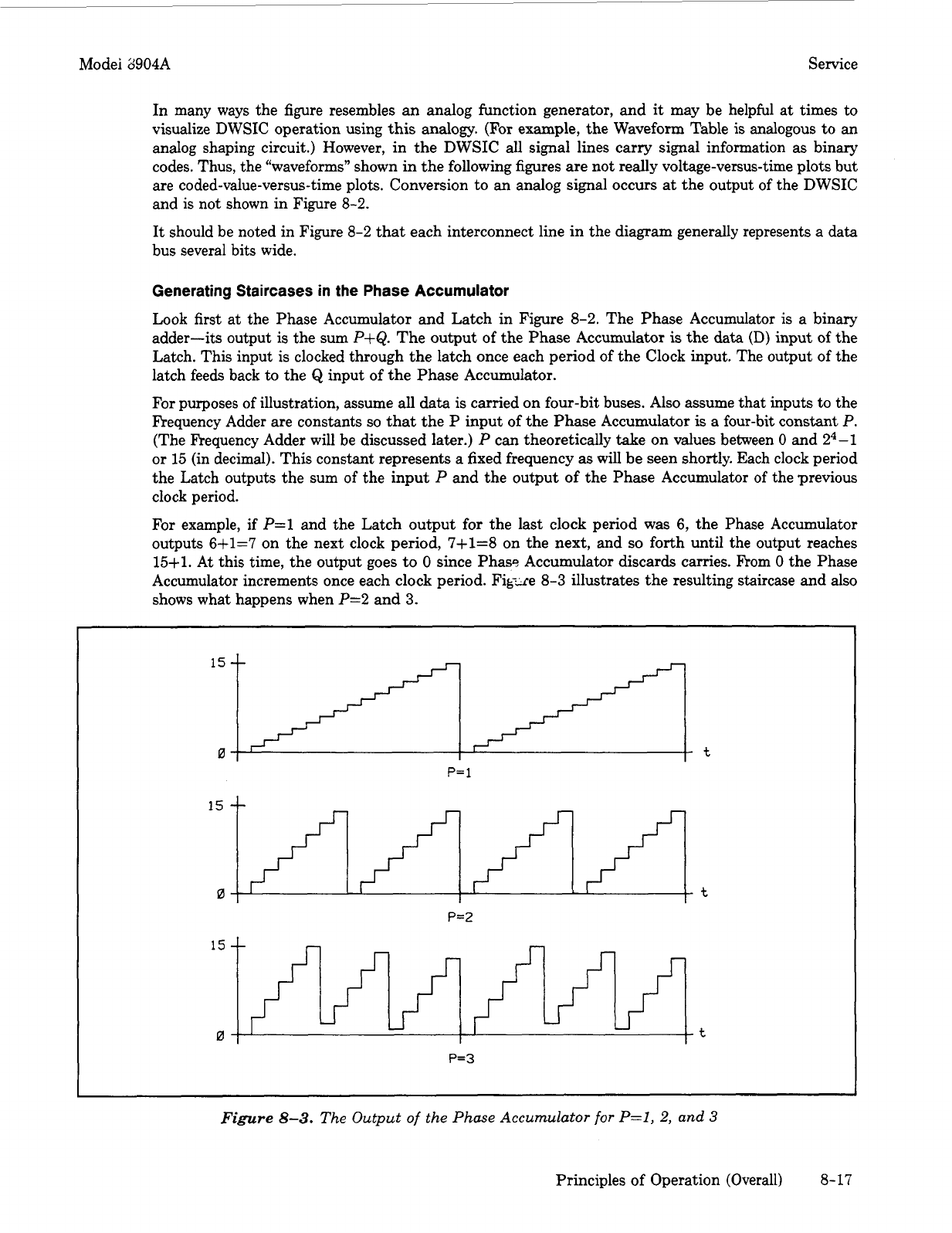
For example, if
P=l
and the Latch output for the last clock period was 6, the Phase Accumulator
outputs
6+1=7
on the next clock period, 7+1=8 on the next, and
so
forth until the output reaches
15fl.
At
this time, the output goes to
0
since Phass Accumulator discards carries.
From
0
the Phase
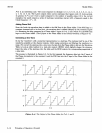
Accumulator increments once each clock period. Fig-re
8-3
illustrates the resulting staircase and
also
shows what happens when P=2 and
3.
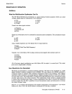
15
0
t
P=
1
15
--
0
t
P=2
P=3
Figure
8-3.
The
Output
of
the Phase
Accumulator
for
P=l,
2,
and
3
Principles of Operation (Overall) 8-17