


Service Model 8904A
3. Partially remove the A2 Digital Assembly as follows. (figure 6-1,
Main Deck Assembly-Top,
may
a.
Unplug all connectors on the
A2
assembly except the
two
soldered-in coaxial cables.
(To
remove the front-most keyboard ribbon cable, lift up on its retainer and push the retainer
forward.)
be helpful.)
b. Remove the single Torx screw securing the
A2
assembly.
c. Carefully lift the
A2
assembly from the seven plastic holding posts by compressing the
small holding tangs with needle-nose pliers, and pulling the board up until the printed
circuit board
is
free from the posts. Carefully rotate the board upward (hinging it from the
left side
as
you face the front panel) until it is vertical. This should allow access to both
sides of the assembly.
1-
BATTERY BACKUP RAM
1
*5Y(F2>
=
I
R25
13
1.96K
+sv
(F2
>
8
4;
I
,L
6.81K
TO
EXTERNAL
POWER SUPPLY
1901-88BB
P
I
"l'
128
1+.7K
1
~~~
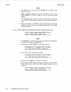
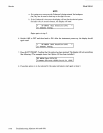
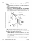
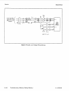
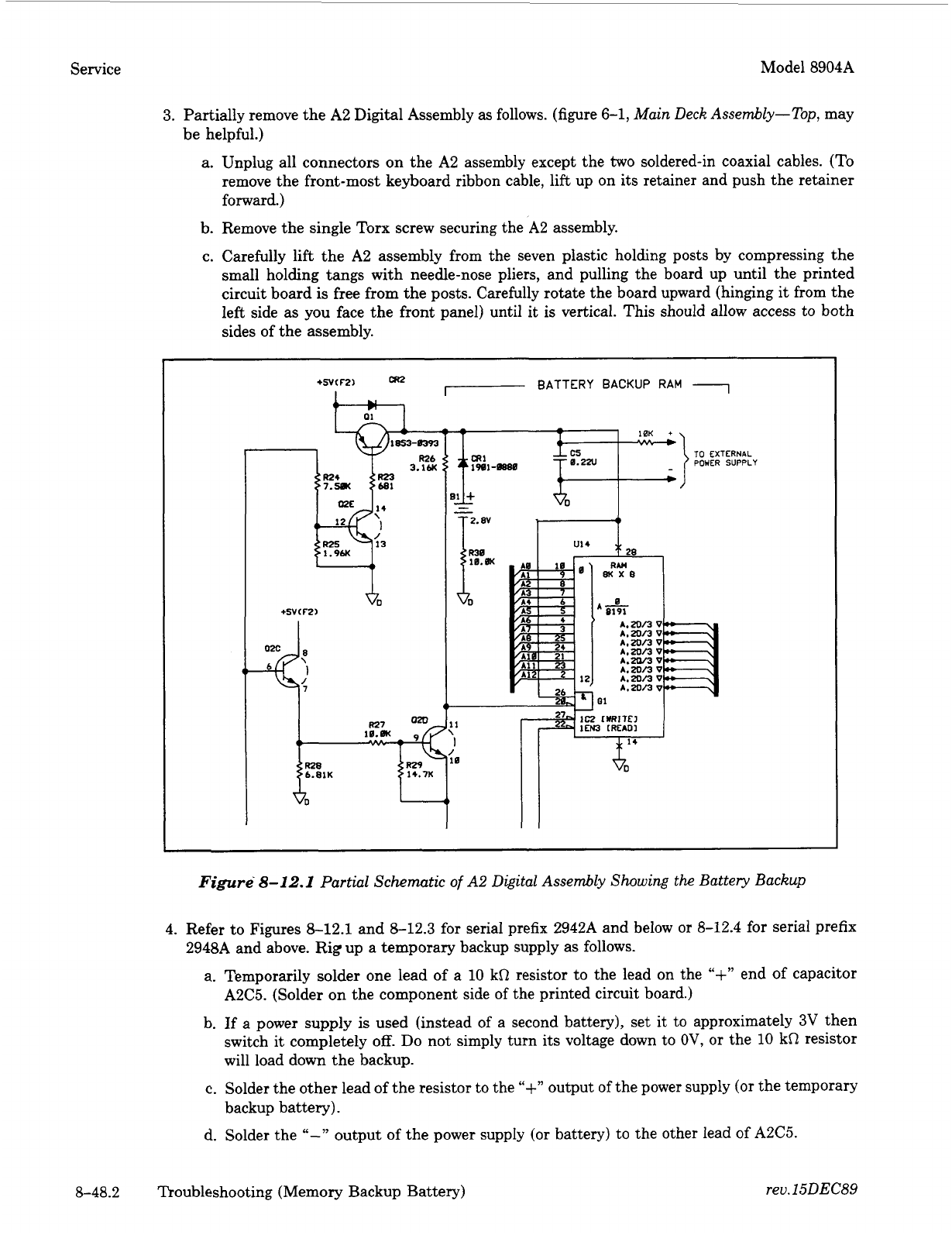
Figure
8-12.1
Partial Schematic
of
A2
Digital Assembly Showing
the
Battery Backup
4. Refer to Figures 8-12.1 and 8-12.3 for serial prefix 2942A and below
or
8-12.4 for serial prefix
a.
Temporarily solder one lead of a 10 kR resistor to the lead on the
"+',
end of capacitor
A2C5. (Solder on the component side
of
the printed circuit board.)
b. If a power supply
is
used (instead
of
a second battery), set it
to
approximately
3V
then
switch it completely
off.
Do not simply turn its voltage down
to
OV,
or
the
10
kR resistor
will load down the backup.
c.
Solder the other lead of the resistor to the
"+"
output
of
the power supply
(or
the temporary
backup battery).
d. Solder the
"-"
output of the power supply
(or
battery)
to
the other lead
of
A2C5.
2948A and above. Rig up
a
temporary backup supply as follows.
8-48.2 Troubleshooting (Memory Backup Battery)
rev.
15DEC89