


Model 8904A Service
A2
DIGITAL
ASSEMBLY
TO
A5 DISPLAY ASSEMBLY INTERFACE
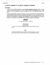
Description
A
failure in the A5 Display Assembly can cause the entire instrument to hang up at power up.
If
this
condition is suspected, measure pin
12
of A2U25 or pin 4 of A2U20 with a high impedance, dc coupled
oscilloscope. TTL pulses should be seen with
1
ps
high and 15
ps
low. (The
signal
is normally a TTL
high.)
To
check the backlighting, measure the connection of the red wire at A2J8 with a high impedance, dc
coupled oscilloscope. (A2J8
is
located in the extreme front, right side
of
A2.) An ac waveform of
80
to
300
Vpp should be observed. The period should be approximately 2 ms. The amplitude will vary with
brightness of the display and
is
adjustable. (See Adjustment
5,
Display Backlighting and Contrast
in
Section
5
of
the
Operation and Calibration Manual.
Display contrast
is
also
adjustable.)
Note that high voltages are measured.
A
no load or short on the backlighting oscillator
of
A2
will damage the drive
circuit.
NOTE
The display backlighting automatically turns
off
approximately
3
minutes
after the last keystroke. Pressing any
key
will turn the backlighting back on.
Troubleshooting (DigitalDisplay Interface) 8-41