


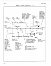

Service Model
8904A
Table
8-1.
Schematic Diagram Notes
(5
of
11)
c
8
21
zm
=1
=m
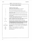
x-Y
(Functional Labels)
MUX
DEMUX
CPU
DIGITAL
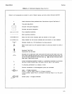
SYMBOLOGY
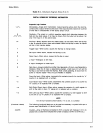
REFERENCE INFORMATION
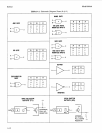
Combinational Logic Symbols and Functions
Summing Junction-Outputs added together at a common point.
AND-All inputs must be active for the output to be active.
OR-One or more inputs being active will cause the output to be active.
Logic Threshold-m or more inputs being active will cause the output to be active
(replace m with a number).
EXCLUSIVE OR-Output will be active when one (and only one) input is active.
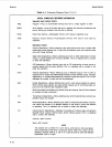
m and only m-Output will be active when m (and only m) inputs are active (replace
m with a number).
Logic Identity-Output will be active only when all or none of the inputs are active
(Le., when all inputs are identical, output will be active).
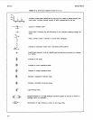
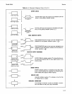
Amplifier-The output will be active only when the input
is
active (can be used with
polarity or logic indicator at input or output to signify inversion).
Signal Level Converter-Input level(s) are different than output level(s).
Bilateral Switch-Binary controlled switch which acts as an on/off switch to analog
or binary signals flowing in both directions. Dependency notation should be used
to indicate affecting/affected inputs and outputs. Note: amplifier symbol (with depen-
dency notation) should be read to indicate unilateral switching.
Coder-Input code
(X)
is
converted to output code (Y) per weighted values or a table.
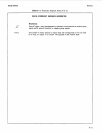
The following labels are to be used as necessary to ensure rapid identification of
device function.
Multiplexer-The output is dependent only on the selected input.
Demultiplexer-Only the selected output is a function
of
the input.
Central Processing Unit
8-8