


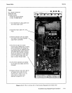
Model 8904A Service
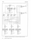
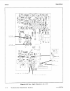
Low-Pass Filters (Service Sheet
2)
Precise construction of the analog waveform from the DAC requires careful filtering. Since the samples
from the DAC are clocked through at approximately 1.67 MHz, sampling theory dictates that a low-pass
filter of approximately 840 kHz
or
less
is
required; in practice the
3
dB
corner will be less than this
but
it
must be greater than 600 kHz, which
is
the upper frequency limit for a sine wave.
The output from the Track-and-Hold Circuit
is
filtered by the Sharp Cutoff Filter (an elliptic function
filter) for sine waves, noise, and some types of complex waveforms (when automatically selected). The
filter
is
flat within
fO.O1
dB
to 600 kHz and has a 3
dB
corner at 670 kHz. Above 670 kHz the filter
rolls
off
rapidly but ripples in the stopband. Adjustments to the filter are made to keep the stopband
attenuation more than 68
dB
beyond 1.07 MHz. For most other waveforms, the Low Overshoot Filter
(a Gaussian type filter) is automatically selected. The filter prevents ringing but limits the useable
frequency range to 50 kHz.
The
Sharp
Cutoff Filter
is
switched by relay K11, the Low Overshoot Filter by K10. The filters are
switched in complement-one
or
the other
is
always in. The filter control signal on line FLC is inverted
by peripheral driver U8A, which controls K10. The output of
U8A
is inverted by
U8B,
which controls
K11. A high on
FLC
switches
in
the
Low
Overshoot Filter.
The filters can be isolated and tested manually by connecting a signal source to 55 and moving jumper
53 to connect point
2
to point
3,
and by connecting a signal analyzer to J6 and moving jumper 57 to
connect point
2
to point
3.
Audio Amplifier (Service Sheet
2)
The Audio Amplifier has
a
precise gain of 8.9 (19
dB).
It
must pass signals from dc to 600 kHz and
maximum levels of 8.9 Vpk with minimum introduction of ripple, distortion, noise,
or
dc offset. The
amplifier is a discrete design of a standard inverting operational amplifier. The gain
is
the ratio of the
parallel combination of R48 and R231 to R47.
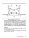
The Audio Amplifier has three stages:
(1)
an input stage (U9, Q14, and QE),
(2)
an intermediate,
high-gain stage (Q20 and Q21), and
(3)
an output driver stage (Q18 and Q19). The virtual ground of
the amplifier
is
the junction of C40 and R49.
In the input stage the ac component
of
the input signal flows through C40 and R56 into the base of
Q14. DC current flows through R49 and
is
amplified (and inverted) by U9. U9 functions as an integrator
providing large gain for dc and low gain for ac. The output of U9
is
fed into the emitter of Q14 through
R53. Q14 differentially sums the ac and dc signals. Components C45, C46, and R57 form a lag-lead (at
1
MHz and 10 MHz) equalization critical for stabilizing the amplifier.
Q20
is
a common-collector amplifier which drives common-base amplifier Q21 to form the intermediate
stage. Q21 drives the collector of Q16 (through Q17) which presents a high-impedance load
to
Q21 and
gives the intermediate stage high gain.
The output stage has unity gain. The complimentary transistor pair Ql8 and Q19 provide sufficient
current to drive the load. Q17 sets and thermally compensates the idle current in Ql8 and Q19. Bias
current for Q17 is generated by Q16. CR6 thermally compensates Q16.
Sine
X/X
Compensation (Service Sheet
2)
The Sine
X/X
Compensation filter compensates the natural roll-off of the sample-generated waveforms
up to
600
kHz. L11 is adjusted for best flatness at 550 kHz. The parasitic load capacitance is accounted
for in the network’s design.
6,
12,
and
24
dB
Attenuators (Service Sheet
3)
Three pi-section attenuators provide 6, 12, and
24
dB
of
programmable attenuation. Each attenuator
has an input impedance of
1
kR. C232 and C504 introduce a load capacitance that
is
constant for all
combinations of attenuation settings.
Principles
of
Operation
(A3)
8-27