


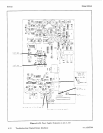

Service Model
8904A
6.
Overvoltage
Control
Checks
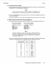
a. On the Multifunction Synthesizer, press
SHIFT PRESET.
After the instrument presets, key in
For
A3
Output Assembly
For
A10 Output Assembly
SHIFT SERVICE SHIFT SERVICE
NEXT NEXT NEXT NEXT
f3
(Memory Map Access)
NEXT NEXT NEXT NEXT
80
80
f3
(Memory Map Access)
NEXT NEXT NEXT NEXT NEXT
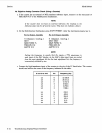
b.
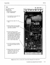
Connect a dc coupled, high-impedance oscilloscope
or
logic probe to pin
12
of
U2.
The voltage
c.
Press
SHIFT.
The voltage should be a TTL high.
should be a
TTL
low.
NOTE
To
repeat this part
of
the check, key in
80
then
SHIFT.
A
beep will be heard
each time
80
is
keyed in.
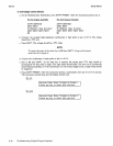
d. Connect the oscilloscope
or
logic probe to pin
11
of
U2.
e. Key in
80
then
SHIFT.
As the shift key
is
pressed, the steady state TTL high should go
momentarily low then back to high. (The logic probe should blink. The trace on an oscilloscope
should blink perceptibly,
or
if
the oscilloscope
is
in the normal trigger mode, a single sweep should
be triggered.)
f.
Press
SHIFT PRESET.
After the instrument presets, momentarily
short
pin
10
of
U2
to ground.
The instrument should beep and the display should read
For
A3:
Reverse Power Relay Tripped on Output
1
Press
any
key
to
reset and continue.
For
A10:
I
Reverse Power Relay Tripped
on
Output
2
I
Press anv kev
to
reset
and
continue.
8-36
Troubleshooting (Digital/Output Interface)