


Model
8904A
Service
Table
8-1.
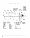
Schematic Diagram Notes
(2
of
11)
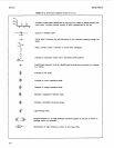
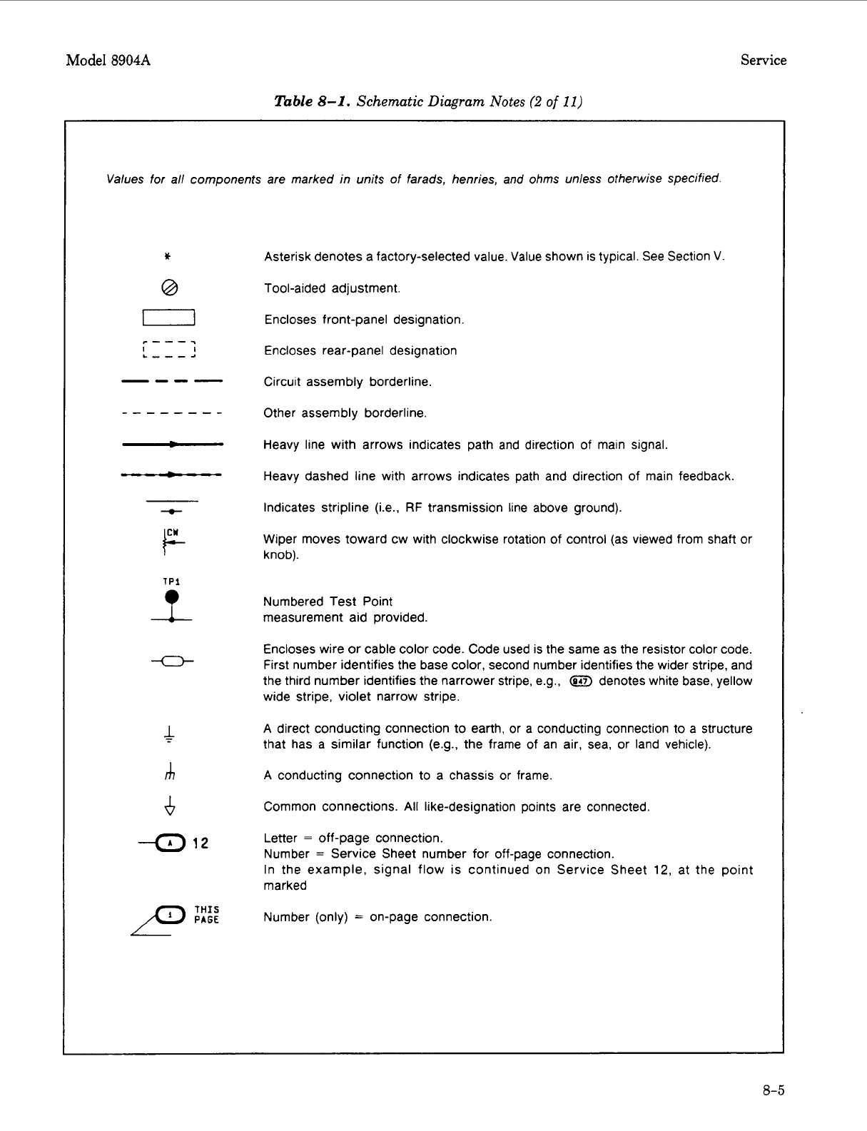
Values for all components are marked
in
units of farads, henries, and ohms unless otherwise specified.
*
0
-0-
F-
U
c
m
-4
12
Asterisk denotes a factory-selected value. Value shown is typical. See Section V.
Tool-aided adjustment.
Encloses front-panel designation.
Encloses rear-panel designation
Circuit assembly borderline
Other assembly borderline.
Heavy line with arrows indicates path and direction of main signal
Heavy dashed line with arrows indicates path and direction of main feedback.
Indicates stripline (Le..
RF
transmission line above ground).
Wiper moves toward cw with clockwise rotation of control (as viewed from shaft or
knob).
Numbered Test Point
measurement aid provided.
Encloses wire
or
cable color code. Code used is the same as the resistor color code.
First number identifies the base color, second number identifies the wider stripe, and
the third number identifies the narrower stripe, e.g.,
(917)
denotes white base, yellow
wide stripe, violet narrow stripe.
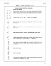
A
direct conducting connection to earth, or a conducting connection to a structure
that has a similar function (e.g., the frame of an air, sea, or land vehicle).
A
conducting connection to a chassis or frame.
Common connections.
All
like-designation points are connected.
Letter
=
off-page connection.
Number
=
Service Sheet number for off-page connection.
In the example, signal flow is continued on Service Sheet
12,
at the point
marked
Number (only)
=
on-page connection
8-5