


Service Model
8904A
CHANNEL
A
I
PHASE
7
P
LATCH
P
-0
C’
c-
‘L
FREOUENCY
6
FREO DATA
9
0
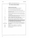
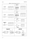
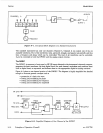
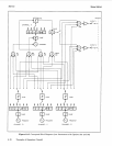
Figure
8-1.
Conceptual
Block
Diagram
of
a Standard Instrument
CLOCK
+
The standard instrument has only one channel-Channel
A.
Channel
A
can output one of the six
available waveforms. Four of the waveforms (sine, sawtooth, triangle,
and
square) are periodic and thus
have a frequency and phase which can be controlled. The level of all waveforms can be controlled.
(Level is controlled in both the DWSIC and the analog output circuits.)
J
AMPLITUDE
MULTIPLIER
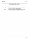
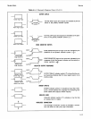
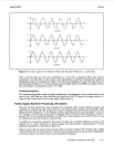
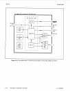
The
DWSIC
The DWSIC, in response to front-panel
or
HP-IB inputs directed
to
the instrument’s internal computer,
generates the basic waveforms (in their
digital
form) for each channel, modulates and combines them
(still in digital form) as requested, and delivers them to the appropriate digital-to-analog converter.
Figure
8-2
shows a one-channel portion
of
the
DWSIC.
The diagram
is
highly simplified but detailed
enough to illustrate general concepts such as
0
generation of a basic sine wave
0
setting and modulating
its
phase
0
setting and modulating
its
frequency
0
setting and modulating
its
amplitude
AM
DATA
2
I
FREOUENCY
ADDER PHASE
I
PHASE WAVEFORM
.
Figure
8-2.
Simplified Diagram
of
One Channel
of
the
D
WSIC
8-16
Principles
of
Operation (Overall)
rev.lOOCT88