


Model
8904A
Service
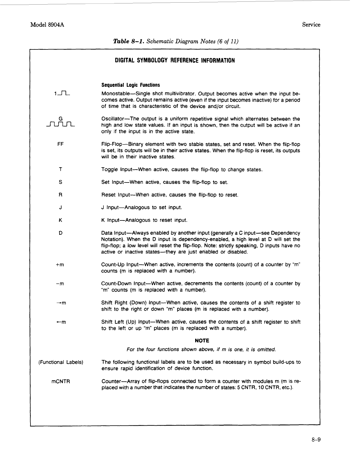
Table
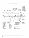
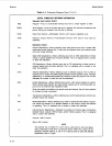
8-1.
Schematic Diagram Notes
(6
of
11)
In
G
nJ--Ln
FF
T
S
R
J
K
D
+m
-m
-m
-m
(Functional Labels)
mCNTR
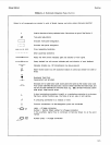
DIGITAL SYMBOLOGY
REFERENCE INFORMATION
Sequential Logic Functions
Monostable-Single shot multivibrator. Output becomes active when the input be-
comes active. Output remains active (even if the input becomes inactive) for a period
of time that is characteristic of the device and/or circuit.
Oscillator-The output is a uniform repetitive signal which alternates between the
high and low state values.
If
an input is shown, then the output will be active if an
only if the input is in the active state.
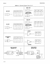
Flip-Flop-Binary element with
two
stable states, set and reset. When the flip-flop
is set, its outputs will be in their active states. When the flip-flop is reset, its outputs
will be in their inactive states.
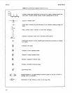
Toggle Input-When active, causes the flip-flop to change states.
Set Input-When active, causes the flip-flop to set.
Reset Input-When active, causes the flip-flop to reset.
J
Input-Analogous to set input.
K
Input-Analogous to reset input.
Data Input-Always enabled by another input (generally a C input-see Dependency
Notation). When the
D
input is dependency-enabled, a high level at
D
will set the
flip-flop; a low level will reset the flip-flop. Note: strictly speaking, D inputs have no
active or inactive states-they are just enabled or disabled.
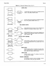
Count-Up Input-When active, increments the contents (count) of a counter by
“m”
counts (m is replaced with a number).
Count-Down Input-When active, decrements the contents (count) of a counter by
“m”
counts
(m
is replaced with a number).
Shift Right (Down) Input-When active, causes the contents of a shift register to
shift to the right or down “m” places
(m
is replaced with a number).
Shift Left (Up) Input-When active, causes the contents
of
a shift register to shift
to the left or up
“m”
places
(m
is replaced with a number).
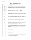
NOTE
For the four functions shown
above,
if
m
is
one,
it is omitted.
The following functional labels are to be used as necessary in symbol build-ups to
ensure rapid identification of device function.
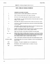
Counter-Array of flip-flops connected to form
a
counter with modules
m
(m
is re-
placed with a number that indicates the number of states:
5
CNTR,
10
CNTR, etc.).
8-9