


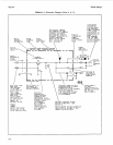

Service
Model
8904A
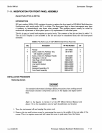
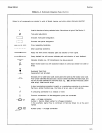
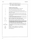
Table
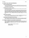
8-1.
Schematic Diagram Notes
(1
of
11)
with adjacent
Test points: symbols
number indicates
are numbered for easy
circuit-path
correlation to schematic
continuation to
diagrams. procedures.
another service
Plug-in sheet
(3.
in
and component location
diagrams. Connection to inf ormat ion; this example).
circuit signifies number Look for same
Board Board Board measuring aid (metal indicates circled letter
Assefnb
ly
pin of socket on the indicated
Circuit
functional
designation
Socket
on A2
information.
Solder point
numbered.
Interconnect
information;
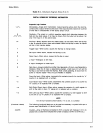
Circled letter
ss2
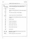
\
Wire'color code.
Code
used
(MIL-STD-661)
is the same
as the resistor
color code.
First number
identifies the
base color.
second number
the wider stripe,
and the third
number the
narrower stripe.
Example:
denotes white base.
*
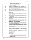
Seriai Prefix
of
instrument to
which Schematic
directly applies.
Reference
designations
within outlined
assemblies are
abbreviated. Full
designation includes
assembly number:
for example.
Rl
of
assembly
A2
is
A2RI.
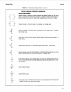
Connector symbols within
the borderlines of board
assemblies signify
connections to the assembly
which are separate
from those made through
the integral plug part
of
the assembly.
Asterisk indicates factory
selected components.
(See
Srrt4nn
<\
"""___..
",
.
Designations
of
other components Value selected for best operation
are complete Value shown
is
average or most
yellow wide stripe. as shown. commonly selected value.
violet narrow stripe
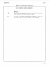
'Large numbers
in lower
right
corners
of
schematic diagrams
are service
sheet numbers.
8-4