


Model
8904A
Instrument Changes
Checking
for
the Shock
Hazard
1.
Unplug the power cord from its rear-panel socket.
2.
Remove the instrument’s top cover by backing out the screw in the center of the rear edge of the
cover. This is a captive screw and will cause the cover to push away from the frame.
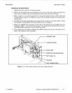
3.
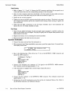
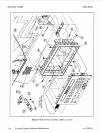
Refer to figure
7-4.
Locate the ground wire.
It
has green insulation with a yellow stripe and
is inside the rear panel in the right rear corner of the instrument beneath the red and silver
warning label.
4.
Carefully slit the black shrink tubing over the ground wire connection to the line socket.
A
sharp
X-acto knife is recommended. (The shrink tubing will not be replaced.)
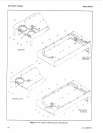
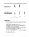
5.
Inspect the soldered wire connection on both ends of the ground wire and compare the wire
wrapping to figure
7-5.
One end of the wire goes
to
the chassis ground lug and the other end to
the socket ground connection on the rear-panel line socket.
6.
If the solder joints are properly wrapped and soldered, replace the top cover and make a quick
check
of
the operation of the instrument.
\
/-WARNING LABEL
BLACK WIRE
GREENVELLOW GROUND
’
/\
MAIN HARNESS (GRAY)
WIRE
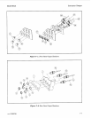
Figure
7-4.
Parts Location (Shown
with
Power
Supply
Removed)
rev.
15DEC89
Firmware Updates/Hardware Modifications
7-11