


Model 8904A Service
8-4.
SERVICE TOOLS, HELPS, AND INFORMATION
Printed Circuit Board Extractor
A
Printed Circuit Board Extractor (HP 08904-00012)
is
supplied as part of this manual. It eases removal
of the A3 and A10 Output Assemblies.
It
hooks under the board or the metal board shield
so
the board
can be pulled
off
the mounting studs.
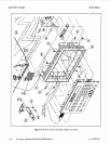
Assembly, Parts, and Cable Locations
The exploded view drawings at the end of Section 6 will assist in locating circuit board assemblies,
cables, and mechanical hardware.
For
the A3 and A10 assemblies only, the locations
of
individual components mounted on printed-circuit
boards are shown adjacent to the schematic diagram on the appropriate service sheet. The part reference
designator
is
the assembly designator plus the part designator.
For
example, A3R9
is
resistor R9
on
the A3 assembly.
For
specific component descriptions and ordering information, refer
to
Table
6-3,
Replaceable Parts,
in Section
6.
Mechanical chassis
parts
have reference designators with no prefix
letter.
Other Service Documents
Service Notes, Manual Updates, and other service literature are available through Hewlett-Packard.
For further information about Manual Updates, refer
to
Volume 1, paragraph
1-11.
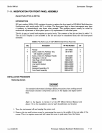
Recommended Test Equipment and Accessories
Test equipment and test accessories required to maintain the Multifunction Synthesizer are listed
in
Table
1-2.
Equipment other than that listed may be used if it meets the listed critical specifications.
8-5.
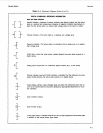
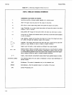
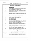
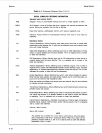
SCHEMATIC SYMBOLOGY AND SCHEMATIC DIAGRAM NOTES
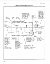
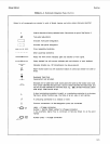
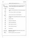
Table 8-1 summarizes the symbology used in presenting many devices found in the instrument. The
logic symbols used in this manual are based on the Institute of Electrical and Electronic Engineers
(IEEE) in IEEE-STD 91-1984,
Graphic Symbols
for
Logic
finctions.
This publication may be
purchased from:
Institute of Electrical and Electronic Engineers
345
East 47th Street
New
York,
NY
10017
8-3