


Service Model
8904A
Table
8-1.
Schematic
Diagram
Notes
(11
of
11)
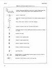
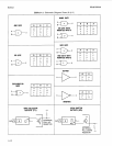
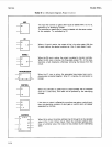
AND
OR
ENABLE
TRANSMISSION
CONTROL
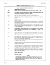
The input that controls or gates other inputs is labeled with a
C
or a
G,
followed by an identifying number.
The controlled or gated input or output is labeled with the same number.
In this example, 1 is controlled by G1.
When a
V
input is active, the output will be in its active state. With the
V
input inactive, the device functions as
if
the
V
input doesn’t exist.
When the
EN
input
is
active, the output
is
enabled to function normally.
When the
EN
input
is
inactive, the three-state output
(V
),
in this case,
becomes
a
high impedance, effectively removing that device from the
circuit.
When the
X1
input is active, the associated input-output pair are bi-
directionally connected together. When X1 is inactive, the connection is
broken.
When the controlled or gated input or output already has a functional
label
(D
is used here), that label
will
be prefixed by the identifying
number.
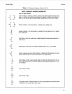
If
the input or output
is
affected by more than one gate or control input,
then the identifying numbers of each gate or control input will appear
separated by commas.
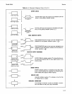
ADDRESS
GA
When
GA
is active, the active address line
(0
through
3)
is the decoded
value of the 1 and
2
binary inputs. When the controlled address lines
have a functional value, that value will be prefixed by the identifying
letter.
i-14