


Model
8904A
Service
Table
8-1.
Schematic Diagram
Notes
(10
of
11)
€3
Active High Input
I
Active High Output
97
Active Low Input
Active
I
Low Output
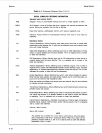
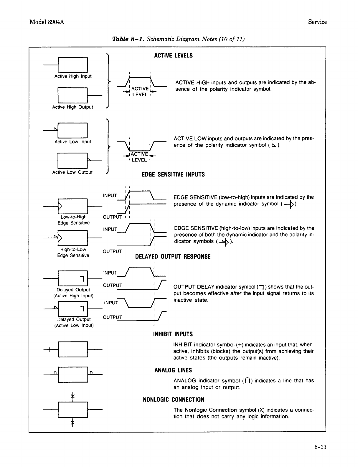
ACTIVE LEVELS
C
A-L
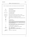
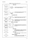
ACTIVE HIGH inputs and outputs are indicated by the ab-
ACTIVE
sence of the polarity indicator symbol.
I
LEVEL
I
ACTIVE
LOW
inputs and outputs are indicated by the pres-
<
+
ence
of
the polarity indicator symbol
(
h).
4
ACTIVE
t
I
LEVEL
I
EDGE SENSITIVE INPUTS
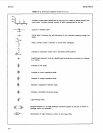
EDGE SENSITIVE (low-to-high) inputs are indicated by the
presence of the dynamic indicator symbol
(
+).
OUTPUT
I
I
Edge Sensitive
EDGE SENSITIVE (high-to-low) inputs are indicated by the
presence of both the dynamic indicator and the polarity in-
dicator symbols
(
+
’.
II
OUTPUT
High-to-Low
Edge Sensitive
DELAYED OUTPUT RESPONSE
I
I
NPUTJ-C
-OUTPUT Delayed Output
I
[
OUTPUT DELAY indicator symbol
(7
)
shows that the out-
put becomes effective after the input signal returns to its
inactive state.
I
(Active High Input)
Delayed Output
(Active Low Input)
I
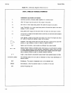
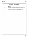
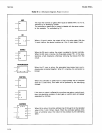
INHIBIT INPUTS
U
INHIBIT indicator symbol
(+)
indicates an input that, when
active, inhibits (blocks) the output(s) from achieving their
active states (the outputs remain inactive).
ANALOG LINES
ANALOG indicator symbol
(n)
indicates a line that has
an analog input or output.
NONLOGIC CONNECTION
The Nonlogic Connection symbol
(X)
indicates a connec-
tion that does not carry any logic information.
8-13