


115
Program operating mode
Page 10 - Filter LFO2
Intensity to B
Specify the depth and direction of the modulation that LFO1
will have on the cutoff frequency of filter B (see “Intensity to
A”).
-99…+99 Parameter value.
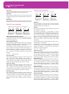
Joystick –Y to A
By moving the joystick in the Y direction (toward yourself),
you can control the depth at which LFO1 modulates the cut-
off frequency of filter A. This parameter specifies the depth
and direction of the control.
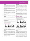
Higher settings of this parameter will produce greater
increases in the effect of LFO1 on the filter when the joystick
is moved toward yourself.
-99…+99 Parameter value.
Joystick –Y to B
By moving the joystick in the Y direction (toward yourself),
you can control the depth at which LFO1 modulates the cut-
off frequency of filter B. This parameter specifies the depth
and direction of the control (see “Joystick –Y to A”).
Filter LFO1 modulation
AMS (Alternate Modulation Source)
Select a source that will control the depth and direction of
cutoff frequency change for both filters A and B. See “AMS
(Alternate Modulation Source) list”.
Intensity to A
Specifies the depth and direction of the effect that “AMS” will
have on filter A.
For example if “AMS” is Joystick +Y, higher settings of this
parameter will allow greater change to be applied to LFO1
when you push the joystick.
-99…+99 Parameter value.
Intensity to B
Specifies the depth and direction of the effect that “AMS” will
have on filter B (see “Intensity to A”).
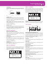
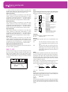
PAGE 10 - FILTER LFO2
Adjusts the depth of the cyclic modulation applied by LFO2
(set on “Page 18 - LFO2”) to the cutoff frequency of filters A
and B. For more information on the parameters see “Page 9 -
Filter LFO1” on page 114.
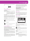
PAGE 11 - FILTER EG
Here you can make settings for the EG that will produce
time-varying changes in the cutoff frequency of filters A and
B for the selected oscillator. The depth of the effect that these
settings will have on the filter cutoff frequency is determined
by the “Velocity” and “Intensity” parameters.
Selected
Use this parameter to select an oscillator to put in edit. Alter-
natively, you can select oscillators using the F1-F4 buttons.
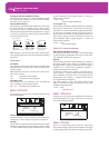
Filter envelope
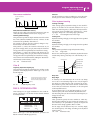
Start/Attack/Break/Sustain/Release Level
These are the envelope segment levels. The result will depend
on the filter that was selected in “Filter Type”. For example,
with the Low Pass Resonance filter, positive (+) values of EG
Intensity will cause the tone to be brightened by positive (+)
levels, and darkened by negative (–) levels.
-99…+99 Level value.
Start Level
This parameter specifies the change in cutoff frequency at the
time of note-on.
Attack Level
This parameter specifies the change in cutoff frequency after
the attack time has elapsed.
Break Point Level
This parameter specifies the change in cutoff frequency after
the decay time has elapsed.
Sustain Level
This parameter specifies the change in cutoff frequency that
will be maintained from after the slope time has elapsed until
note-off occurs.
Release Level
This parameter specifies the change in cutoff frequency that
will occur when the release time has elapsed.
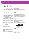
Attack/Decay/Slope/Release Time
These parameters specify the time over which the filter
change will occur.
0…99 Time value.
Attack Time
This parameter specifies the time over which the level will
change from note-on until the attack level is reached.
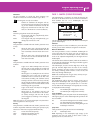
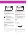
Change in cutoff
Low setting High setting
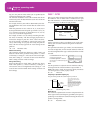
Selected: Osc1
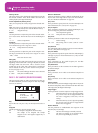
Intensity to A: +0
Intensity to B: +0
Joystick -Y to A: +5
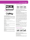
Filter LFO2|Osc1
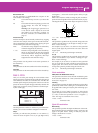
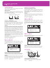
Selected: Osc1
Start Level: +99
Attack Time: 73
Attack Level: +95
FilterEG |Osc1
Note-on
Note-off
Attack
Time
Start
Level
Decay
Time
Release
Time
Release
Level
Attack Level
The specified
cutoff
frequency
Sustain Level
Time
Break
Point
Level
Slope
Time