


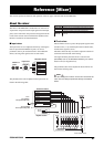
Reference [Mixer]
ZOOM MRS-802
70
HINT
To record the signal processed by the send/return effect on
a track, you can use bounce recording while the respective
[INPUT 1]/[INPUT 2] key is on (
→ p. 39).
1.
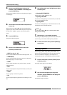
Press the [CHORUS/DELAY] key or [REVERB] key
to select a patch for the send/return effect.
The display changes and shows the currently selected patch
of the selected effect (chorus/delay or reverb).
2.
Turn the dial to select the patch you want to use.
You can also select a patch by using the PATCH SELECT
[
Q]/[W] keys in the effect section.
When you have selected the patch, press the [EXIT] key to
return to the main screen.
3.
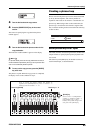
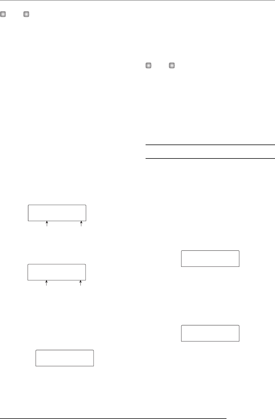
Press the [TRACK PARAMETER] key in the track
parameter section and use the cursor up/down
keys to bring the following indication onto the
display.
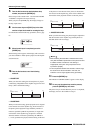
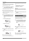
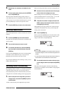
•To adjust the chorus/delay send level
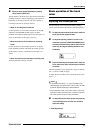
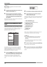
•To adjust the reverb send level
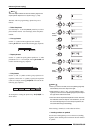
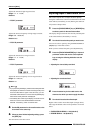
4.
Press the [INPUT 1] or [INPUT 2] key in the input
section.
The input mixer (INPUT) is selected as target for setting the
send level.
5.
Turn the dial to select the effect depth.
Higher values result in more effect depth (stronger effect).
The range and default values for the parameters are shown
below.
• CHORUS/DELAY SEND: 0 - 100 (default: 0)
• REVERB SEND: 0 - 100 (default: 0)
HINT
When the send level is shown on the display, pressing the
[ENTER] key will turn the signal output to the send return
effect off. Pressing the key once more will turn the signal on
again.
6.
When you have finished making settings, press the
[EXIT] key.
The unit returns to the main screen.
Adjusting the pan/balance
This section explains how to adjust the pan (stereo position)
of the signal sent from the input mixer to the MASTER
OUTPUT jacks and the recording tracks, or the balance (the
volume balance between two channels).
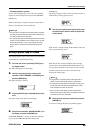
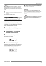
1.
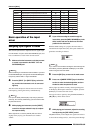
Press the [TRACK PARAMETER] key in the track
parameter section and use the cursor up/down
keys to bring the following indication onto the
display.
2.
Press the [INPUT 1] or [INPUT 2] key in the input
section.
The input mixer (INPUT) is selected as target for panning
adjustment.
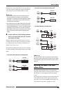
3.
Turn the dial to edit the value of the PAN parameter.
The PAN parameter can be adjusted in a range of L100 (far
left) - 0 (center) - R100 (far right).
Parameter Setting value
TR1
TR1
CHO SEND
CHO SEND
0
Parameter Setting value
TR1
TR1
REV SEND
REV SEND
0
INPUT
INPUT
CHO SEND
CHO SEND
0
TR1
TR1
PAN
PAN
0
INPUT
INPUT
PAN
PAN
0