


4
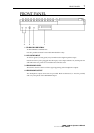
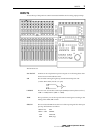
REAR PANEL
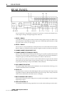
REAR PANEL
The rear panel has a comprehensive selection of connectors to interface the DPS24 with a
wide range of analogue and digital equipment. These are:
1. INPUTS - BANK A
Across the top of the rear panel are the two banks of analog inputs. The top row (Bank A) are
balanced inputs on XLR/TRS jack combos. These can accommodate XLR connectors or TRS
(tip, return, send - stereo) 1/4" jack plugs.
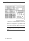
2. INPUTS - BANK B
The second row of inputs (Bank B) are TRS jacks that can accommodate balanced inputs.
Banks A and B are switched from the front panel using the switches across the top of the panel
3. CHANNEL INSERT SENDS/DIRECT OUT
4. CHANNEL INSERT RETURNS/ADC INPUTS
Inputs 1-4 also feature balanced insert points allowing you to patch in professional external
processors such as noise gates, compressors, etc.. Although each channel of the DPS24 has a
compressor/gate, you may want to use external valve units or other devices.
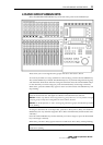
The channel insert sends (3) can also be used as balanced direct outputs and the channel
insert returns (4) can also be used to accept external pre-amps or 19" 'channel strips' therefore
by-passing the internal pre-amps on the DPS24 for these channels.
5. SCSI CONNECTOR OPTION
The optional 68pin Wide-SCSI interface IB-24SCSI may be installed here allowing you to
connect external SCSI drives to the DPS24.
6. DIGITAL I/O
These RCA phono connectors offer SPDIF digital audio input and output. The input is freely
assignable to channels within the DPS24 and the output can accept a wide variety of internal
audio sources (the default is the master stereo L/R output).
7. MULTI-PURPOSE LIGHT PIPE I/O
These optical connectors can be configured to carry either stereo SPDIF or 8-channel ADAT˛
digital input/output.
8. AUXILLIARY SENDS 1-4
AUX SENDS 1-4 default to being output here for use with external effects processors. How-
v1.6 Operator’s Manual