


89
MODEL 3081 pH/ORP SECTION 12.0
TROUBLESHOOTING
SECTION 12.0
TROUBLESHOOTING
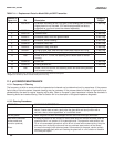
12.1 WARNING AND FAULT MESSAGES
12.2 CALIBRATION ERRORS
12.3 TROUBLESHOOTING - GENERAL
12.4 TROUBLESHOOTING WHEN A DIAGNOSTIC MESSAGE IS SHOWING
12.5 TROUBLESHOOTING WHEN NO DIAGNOSTIC MESSAGE IS SHOWING
12.6 SYSTEMATIC TROUBLESHOOTING
12.7 DISPLAYING DIAGNOSTIC VARIABLES
12.8 TESTING THE TRANSMITTER BY SIMULATING pH
12.9 FACTORY ASSISTANCE AND REPAIRS
12.1 WARNING AND FAULT MESSAGES
The Model 3081 pH/ORP transmitter continuously monitors the measurement
loop (sensor and transmitter) for conditions that cause erroneous measurements.
When a problem occurs, the transmitter displays either a warning or fault mes-
sage. A warning alerts the user that a potentially system disabling condition exists.
If the condition causing the problem is not corrected, there is a high probability
that the system will soon fail. A fault alerts the user that a system disabling con-
dition exists. If a fault message is showing, all measurements should be regard-
ed as erroneous.
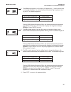
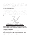
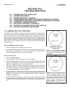
When a WARNING condition exists:
1. The main display remains stable; it does not flash.
2. A warning message appears alternately with the temperature/output display.
See Figure 12-1. See Section 12.4 for an explanation of the different warn-
ings and suggested ways of correcting the problem.
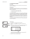
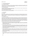
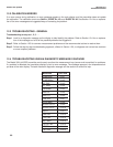
When a FAULT exists:
1. The main display flashes.
2. The words FAULT and HOLD appear in the main display.
3. A fault message appears alternately with the temperature/output display. See
Figure 12-2. See Section 12.4 for an explanation of the different fault mes-
sages and suggested ways of correcting the problem.
4. The output current will remain at the present value or go to the programmed
fault value. See Section 8.3 Output Ranging for pH Measurements, or Section
10.3 Output Ranging for ORP Measurements for details on how to program
the current generated during a fault condition.
5. If the transmitter is in HOLD when the fault occurs, the output remains at the
programmed hold value. To alert the user that a fault exists, the word FAULT
appears in the main display, and the display flashes. A fault or diagnostic
message also appears.
6. If the transmitter is simulating an output current when the fault occurs, the
transmitter continues to generate the simulated current. To alert the user that
a fault exists, the word FAULT appears in the display, and the display flash-
es.
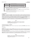
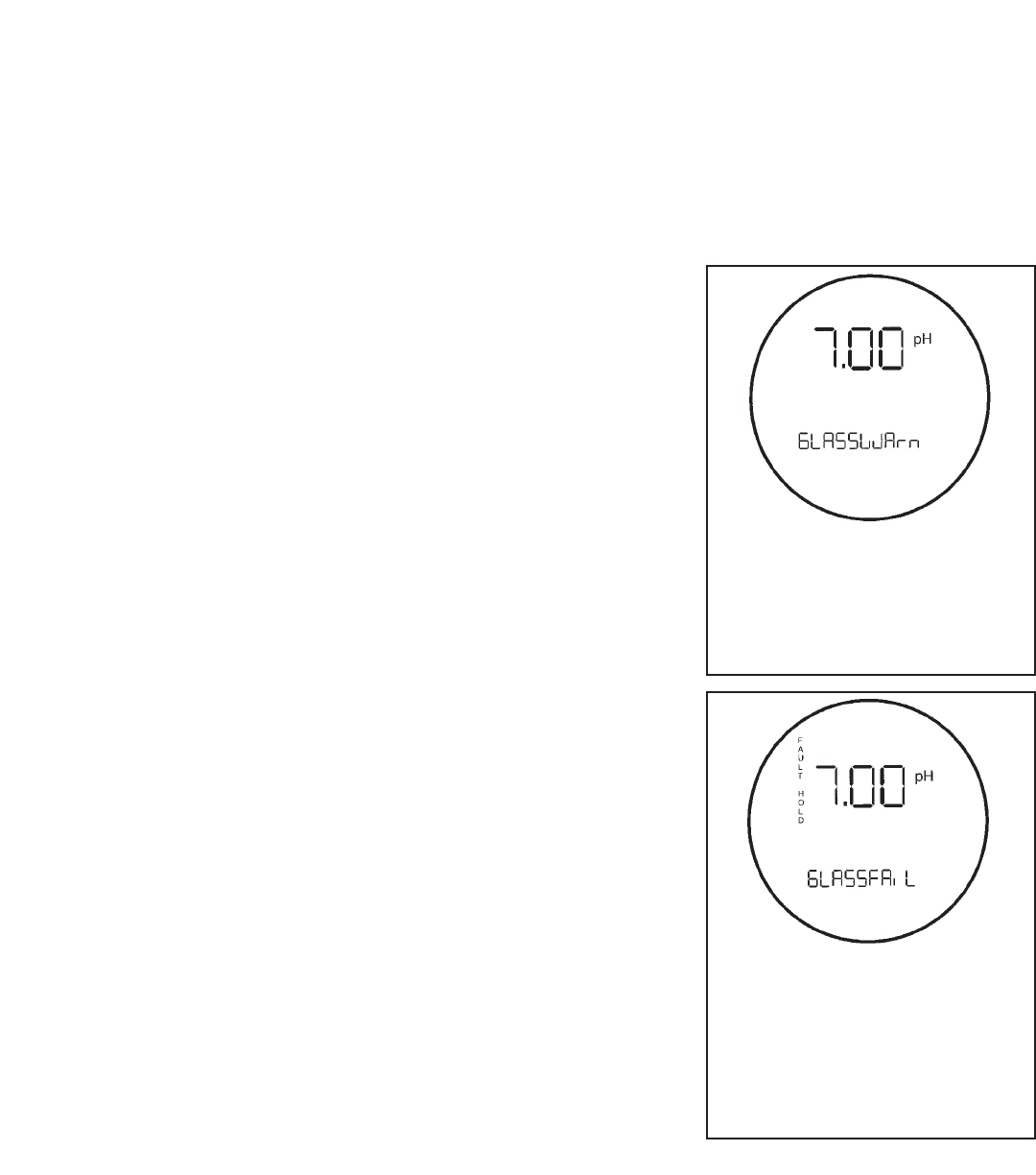
FIGURE 12-1. Warning
Annunciation
When a non-disabling problem
occurs, a warning message appears
alternately with the temperature/ out-
put display.
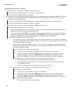
FIGURE 12-2. Fault Annunciation
When a disabling condition, a fault,
occurs, the display appears as pic-
tured above. To further alert the user
that measurements are in error, the
display flashes. Diagnostic mes-
sages appear in the temper-
ature/output area on the screen.