


MODEL 3081 pH/ORP SECTION 3.0
WIRING
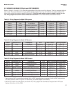
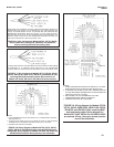
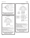
3.2 WIRING DIAGRAMS FOR pH and ORP SENSORS
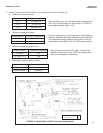
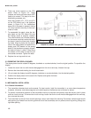
Refer to Tables 3-1 through 3-12 to locate the appropriate wire function and wiring diagram. There is a separate table for
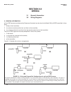
each model. The sensor models having the highest number appear first. If you do not know the model number of the
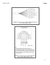
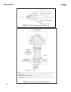
sensor, refer to the flow charts on pages 28 through 30. Only the model option numbers needed to select the cor-
rect wiring diagram are shown. Other numbers are not shown. For all other sensors, see sensor manual.
Table 3-1. Wiring Diagrams for Model 399 sensors
Sensor Junction Box Preamplifier RTD Wire Function Wiring Diagram
399-02 none in transmitter 3K Balco** Figure 3-2 Figure 3-4
399-02 remote in remote junction box 3K Balco** Figure 3-2 Figure 3-5
399-09* none in transmitter Pt 100 Figure 3-2 Figure 3-4
399-09* remote in remote junction box Pt 100 Figure 3-2 Figure 3-5
399-09-62 none in transmitter Pt 100 Figure 3-3 Figure 3-4
399-09-62 remote in remote junction box Pt 100 Figure 3-3 Figure 3-5
399-33 (ORP only) none in transmitter Pt 100 Figure 3-21 Figure 3-22
Table 3-2 Wiring Diagrams for Model 397 Sensors
Sensor Junction Box Preamplifier RTD Wire Function Wiring Diagram
397-50 none in transmitter 3K Balco** Figure 3-6 Figure 3-8
397-50 remote in remote junction box 3K Balco** Figure 3-6 Figure 3-9
397-54* none in transmitter Pt 100 Figure 3-6 Figure 3-8
397-54* remote in remote junction box Pt 100 Figure 3-6 Figure 3-9
397-54-62 none in transmitter Pt 100 Figure 3-7 Figure 3-8
397-54-62 remote in remote junction box Pt 100 Figure 3-7 Figure 3-9
Table 3-3 Wiring Diagrams for Model 396R Sensors
Sensor Junction Box Preamplifier RTD Wire Function Wiring Diagram
396R-50 remote in remote junction box 3K Balco** Figure 3-10 Figure 3-12
396R-50 none in transmitter 3K Balco** Figure 3-10 Figure 3-11
396R-50-60 sensor-mounted in sensor-mounted junction box 3K Balco** Figure 3-6 Figure 3-9
396R-54 none in transmitter Pt 100 Figure 3-10 Figure 3-11
396R-54 remote in remote junction box Pt 100 Figure 3-10 Figure 3-12
396R-54-60 sensor-mounted in sensor-mounted junction box Pt 100 Figure 3-7 Figure 3-9
396R-54-61 sensor-mounted in sensor-mounted junction box Pt 100 Figure 3-10 Figure 3-12
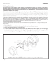
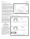
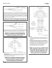
* Sensors have a BNC connector that the Model 3081 pH/ORP transmitter does not accept. Cut off the BNC and terminate
the coaxial cable as shown in Figure 3-23. Alternatively, use a BNC adapter (PN 9120531).
** Set the RTD jumper to the 3K position (see Section 2.2). Also, program the transmitter to recognize the 3K RTD (see
Section 8.5 for pH or 10.5 for ORP).
15