


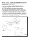

QUICK START GUIDE FOR MODEL 3081pH/ORP
Before using this Quick Start Guide, please read “WHAT YOU NEED TO KNOW BEFORE
INSTALLING AND WIRING A ROSEMOUNT ANALYTICAL SENSOR TO THE MODEL 3081
pH/ORP TRANSMITTER” on the preceding page.
Section 1.1 Setup for the Models 381+-52, 385+-04, 396P-02-54, 396P-02-55 and 396R-54 without a junction box
A. The factory setting of the preamplifier switch is in the appropriate location, so no adjustment is necessary.
B. Mount the transmitter in the desired location. Most installations use PN 2002577, pipe mounting bracket.
C. Continue the start up with Section 2 Wiring.
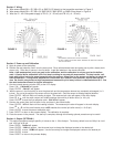
Section 1.2 Setup for Sensor Models 381+-55, 385+-03, and 396P-01-55 without a junction box
A. This section shows how to set the preamplifier switch and should be done prior to installation of the transmitter.
B. Loosen the cover lock nut on the Model 3081pH/ORP transmitter until the tab disengages from the circuit end cap.
Unscrew and remove the cap. Unscrew the three bolts holding the circuit board stack in the enclosure.
C. Pull up on the display board. Do not disconnect the ribbon cable between it and the CPU board. The CPU and analog
boards are joined by a pin and socket connector along the bottom edge of the boards. Carefully pull the boards apart and
remove the CPU board. The analog board is on the bottom and remains in the enclosure. See Figure 1 below.
D. The analog board is shaped like a circle with an arc missing. Directly opposite the straight side is a slide switch. Change
the switch position to the "sensor or j-box" setting by sliding the switch closer to the edge of the board. See Figure 2 below.
E. To reassemble the stack, place the display board on the CPU board. Be sure the display board is properly oriented. The
small square window (the infrared detector for the remote controller) marks the top of the board. Insert the three bolts
through the holes. Align the bolts with the standoffs on the analog board and position the display and CPU boards on the
analog board. SIf the boards are properly aligned, the bolts will drop in place. Press along the bottom of the stack to seat
the pin and socket connector. Tighten the bolts, replace the cap and cover lock nut.
F. Mount the transmitter in the desired location. Most installations use PN 2002577, pipe mounting bracket.
FIGURE 2
FIGURE 1