


MODEL 3081 pH/ORP SECTION 12.0
TROUBLESHOOTING
12.7 DISPLAYING DIAGNOSTIC VARIABLES
12.7.1 Purpose
This section describes how to display the diagnostic variables listed below:
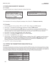
DIAGNOSTIC MEASUREMENTS DIAGNOSTIC MESSAGES
1. Sensor voltage in mV (InPut) 1. Software version (VEr)
2. Glass impedance in megohms (GIMP) 2. Display last three fault messages (ShoW FLt)
3. Reference impedance in kilohms* (rIMP)
4. Temperature in °C (tEMP)
* For high impedance reference electrodes,
the reference impedance is in megohms.
For an explanation of the meaning of diagnostic messages, refer to Section 8.4. Displays are read only.
12.7.2 Procedure
1. Enter the Diagnostic menu by pressing DIAG on the IRC. Sensor voltage in mV (InPut) appears.
2. Press NEXT . The temperature corrected glass impedance in megohms (GIMP) appears.
3. Press NEXT . The reference impedance (rIMP) appears. For conventional low impedance silver/silver chloride
reference electrodes, the reference impedance has units of kilohms. For the rare occasions when a high impedance
reference is used, the units are megohms. See Sections 8.4 (for pH) and 10.4 (for ORP) for more information.
4. Press NEXT . The model number and software version (Ver) appears.
5. Press NEXT . The temperature (tEMP) measured by the sensor appears.
6. Press NEXT . The ShoW Flt sub-menu appears.
7. Press ENTER . The most recent fault message appears in the display. Press NEXT repeatedly to scroll through the
stored messages. The transmitter only remembers the three most recent messages. nonE appears if there are no
faults. Pressing EXIT clears all the stored messages and returns the transmitter to the ShoW Flt display. If the
transmitter loses power, all stored warning and fault messages are lost.
8. Press EXIT to return to the process display.
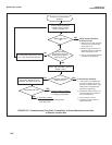
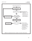
12.8 TESTING THE TRANSMITTER BY SIMULATING THE pH.
12.8.1 General.
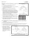
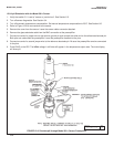
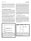
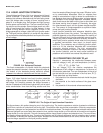
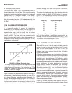
This section describes how to simulate a pH input into the 3081 pH/ORP transmitter. pH is directly proportional to voltage.
To simulate the pH measurement, connect a standard millivolt source to the transmitter. If the transmitter is working prop-
erly, it will accurately measure the input voltage and convert it to pH. Although the general procedure is the same, the
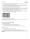
wiring details depend on the location of the preamplifier. Consult the table to find the correct procedure.
Preamplifier located in Section
Transmitter 12.8.2
Remote junction box 12.8.3
Sensor-mounted junction box 12.8.3
Sensor (Model 381+ only) 12.8.4
Sensor (all other models) 12.8.5
110