


58
MODEL 3081 pH/ORP SECTION 8.0
PROGRAMMING FOR pH MEASUREMENTS
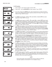
8.3 OUTPUT RANGING
8.3.1 Purpose
This section describes how to do the following:
1. assign pH values to the 4 and 20 mA outputs,
2. set the output current generated by the transmitter during hold,
3. set the output current generated by the transmitter when a fault is detected,
4. control the amount of dampening on the output signal.
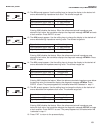
8.3.2 Definitions
1. CURRENT OUTPUTS. The transmitter provides a continuous 4 - 20 mA output directly pro-
portional to the measured pH. Any pH value between 0 and 14 can be assigned to the low out-
put (4 mA) and the high output (20 mA).
2. HOLD. During calibration and maintenance the transmitter output may be outside the normal
operating range. Placing the transmitter on hold prevents false alarms or the unwanted oper-
ation of chemical dosing pumps. The transmitter output can be programmed to remain at the
last value or to generate any current between 3.80 and 22.0 mA. During hold, the transmitter
displays the present pH and temperature. The word HOLD appears in the display.
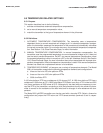
3. FAULT. A fault is a system disabling condition. When the transmitter detects a fault, the fol-
lowing happens:
a. The display flashes.
b. The words FAULT and HOLD appear in the main display.
c. A fault or diagnostic message appears in the temperature/current display area.
d. The output signal remains at the present value or goes to the programmed fault value.
Permitted values are between 3.80 and 22.00 mA.
e. If the transmitter is in HOLD when the fault occurs, the output remains at the programmed
hold value. To alert the user that a fault exists, the word FAULT appears in the main dis-
play, and the display flashes. A fault or diagnostic message also appears.
f. If the transmitter is simulating an output current when the fault occurs, the transmitter con-
tinues to generate the simulated current. To alert the user that a fault exists, the word
FAULT appears in the display, and the display flashes.
g. If a sensor fault occurs, a 1 mA signal appears at TB-14 (see Section 2.5.2). Sensor faults
are rEF FAIL, rEF WArn, GLASSFAIL, and GLASSWARrn. See Section 12.0 for more
information about sensor faults.
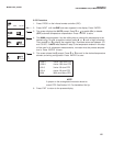
4. DAMPEN. Output dampening smooths out noisy readings. But it also increases the response
time of the output. To estimate the time (in minutes) required for the output to reach 95% of
the final reading following a step change, divide the setting by 20. Thus, a setting of 140
means that, following a step change, the output takes about seven minutes to reach 95% of
final reading. The output dampen setting does not affect the response time of the process dis-
play. The maximum setting is 255.