


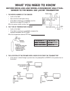
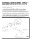
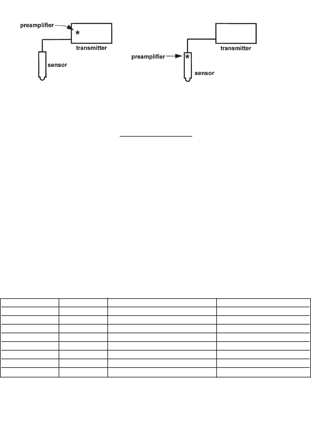
• If the sensor is wired directly to the transmitter, the preamplifier can be in either the sensor
or the transmitter.
• Look at the wires in the sensor cable. A GREEN wire means the preamplifier is in the sen-
sor. An coaxial cable means the preamplifier is in the transmitter. A coaxial cable is an
insulated wire surrounded by a braided metal shield. The wire terminates in either a BNC
connector or an ORANGE wire with a CLEAR shield.
Write the preamplifier location here
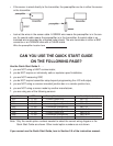
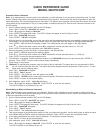
CAN YOU USE THE QUICK START GUIDE
ON THE FOLLOWING PAGE?
Use the Quick Start Guide if . . .
1. you are NOT using a HART communicator,
2. you do NOT require an intrinsically safe or explosion-proof installation,
3. you are NOT measuring ORP,
4. you do NOT require transmitter setup beyond programming the 4-20 mA output,
5. you are NOT using a a sensor-mounted junction box or a remote junction box,
6. you are NOT using a sensor made by another manufacturer,
7. you are using one of the following sensors:
Note: Only the model option numbers needed to select the correct wiring diagram in the
Quick Start Guide are shown. Other model option numbers are not shown.
If you cannot use the Quick Start Guide, turn to Section 2.0 of the instruction manual.
Base Model RTD Preamplifier located Model Option (note)
381+ Pt 100 in sensor (green wire) 381+ -55
381+ Pt 100 in transmitter (orange wire) 381+ -52
385+ Pt 100 in sensor (green wire) 385+ -03
385+ Pt 100 in transmitter (orange wire) 385+ -04
396P Pt 100 in transmitter (orange wire) 396P-02-54
396P Pt 100 in sensor (green wire) 396P-01-55
396P Pt 100 in transmitter (orange wire) 396P-02-55
396R Pt 100 in transmitter (orange wire) 396R-54