


112
MODEL 3081 pH/ORP SECTION 12.0
TROUBLESHOOTING
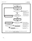
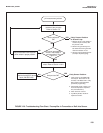
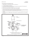
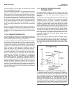
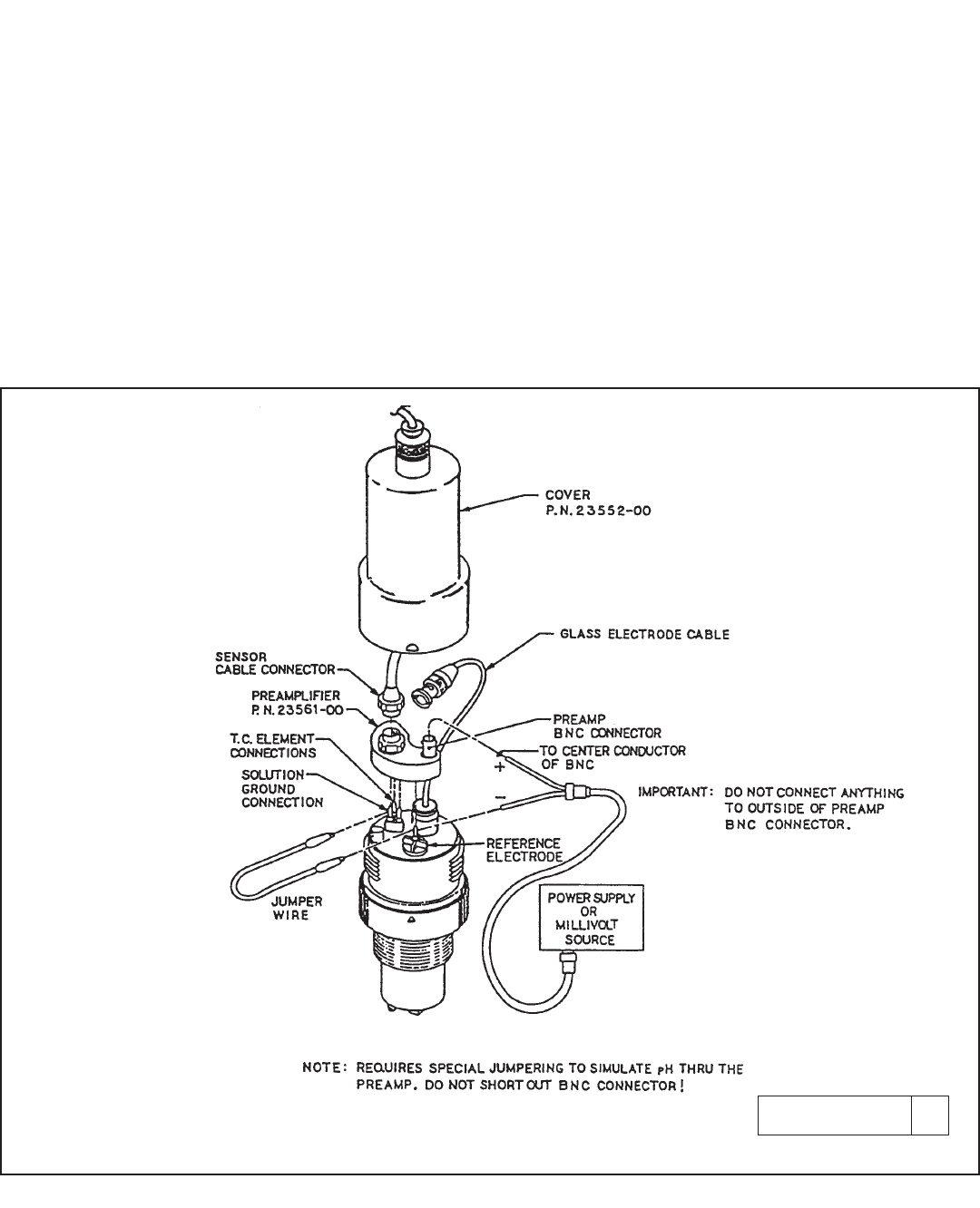
FIGURE 12-9. Simulate pH through Model 381+ Sensor Preamplifier
DWG. NO. REV.
40381+05 A
12.8.4 pH Simulation with the Model 381+ Sensor
1. Verify that switch S-1 is set to "sensor or junction box". See Section 2.2.
2. Turn off sensor diagnostics. See Section 8.4.
3. Turn off automatic temperature compensation. Set manual temperature compensation to 25°C. See Section 8.5.
4. Refer to Figure 12-9 for connections to the sensor.
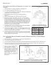
5. Remove the cover from the sensor. Leave the sensor cable connector attached.
6. Remove the glass electrode cable from the BNC connection at the preamplifier.
7. Connect one end of a jumper wire to the solution ground pin and connect the other end to the reference electrode pin.
Both pins are underneath the preamplifier. Leave the preamplifier installed on the pins.
8. Connect one end of a second jumper wire to the reference electrode pin. Be sure the preamplifier remains connected
to the pins.
9. Press DIAG on the IRC. The InPut voltage in millivolts will appear in the temperature-output area. The main display
will show pH.