


85
MODEL 3081 pH/ORP SECTION 11.0
MAINTENANCE
SECTION 11.0
MAINTENANCE
11.1 OVERVIEW
This section gives general procedures for routine maintenance of the 3081 pH/ORP transmitter and pH and ORP
sensors. The transmitter needs almost no routine maintenance. Sensors require periodic inspection and cleaning.
The calibration of the transmitter-sensor combination should be checked regularly, and the loop recalibrated if
necessary.
11.2 TRANSMITTER MAINTENANCE
Periodically clean the transmitter window with household ammonia or glass cleaner. The detector for the infrared
remote controller is located behind the window at the top of the transmitter face. The window in front of the detec-
tor must be kept clean.
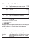
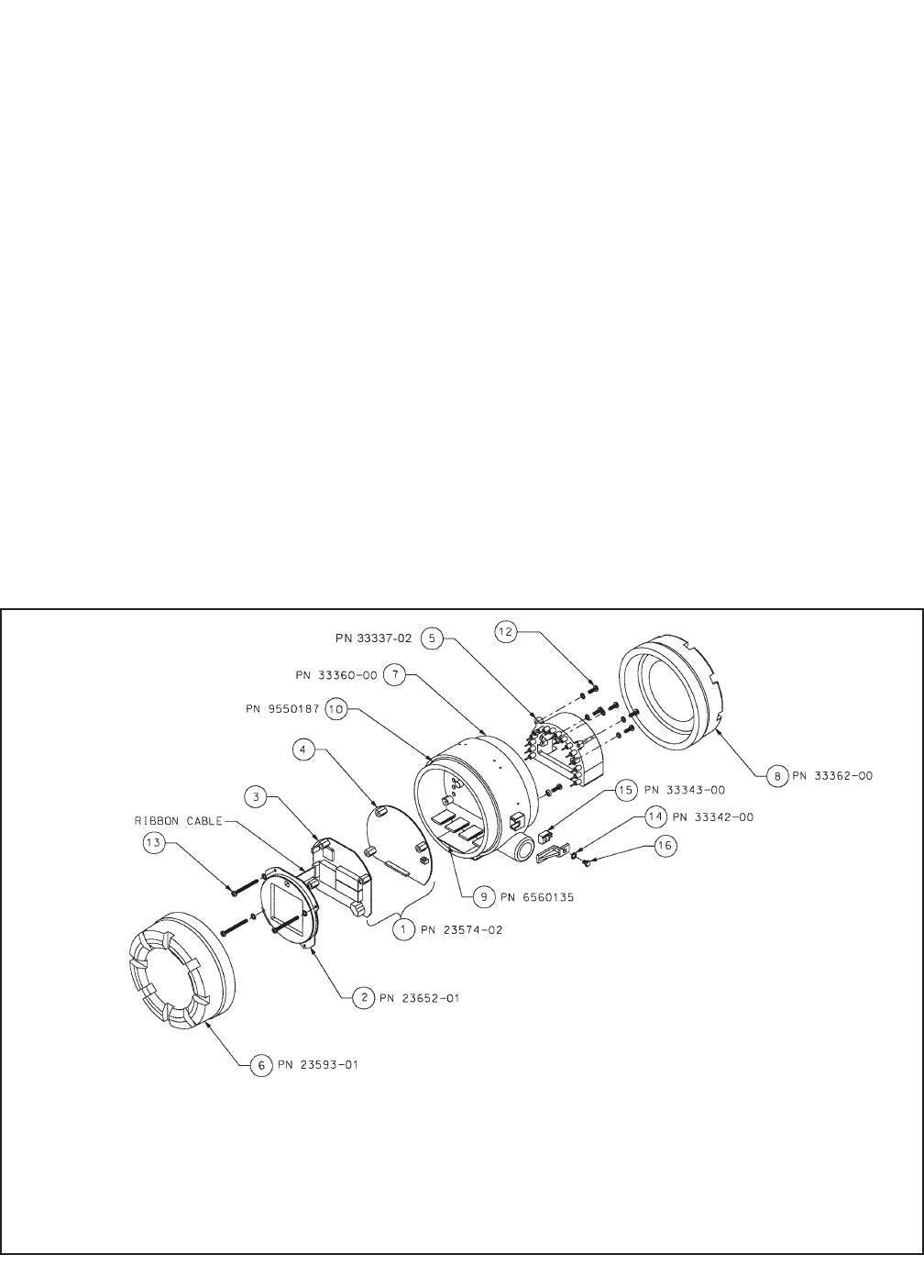
Most components of the transmitter are replaceable. Refer to Figure 11-1 and Table 11-1 for parts and part numbers.
11.1 Overview
11.2 Transmitter Maintenance
11.3 pH Sensor Maintenance
11.4 ORP Sensor Maintenance
11.5 Calibration
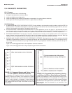
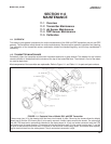
FIGURE 11-1. Exploded View of Model 3081 pH/ORP Transmitter
Three screws (part 13 in the drawing) hold the three circuit boards in place. Removing the screws allows the display
board (part 2) and the CPU board (part 3) to be easily removed. A ribbon cable connects the boards. The cable plugs
into the CPU board and is permanently attached to the display board. A 16 pin and socket connector holds the CPU
and analog (part 4) boards together. Five screws hold the terminal block (part 5) to the center housing (part 7), and the
16 pins on the terminal block mate with 16 sockets on the back side of the analog board. Use caution when separat-
ing the terminal block from the analog board. The pin and socket connection is tight.