


96
MODEL 3081 pH/ORP SECTION 12.0
TROUBLESHOOTING
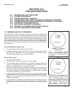
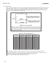
B. Check the sensor.
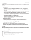
Refer to the wiring diagrams in Section 3.0 to identify the RTD leads. Disconnect the RTD leads and measure the
resistances shown in Figure 12-3. The measured resistance should agree with the value in Table 12-1 to within
about 1%. If the measured resistance is appreciably different (between 1 and 5%) from the value shown, the
discrepancy can be calibrated out. See Section 8.5.
If a connection is open or shorted and it should not be, the sensor has failed. Replace the sensor.
If the RTD is different from what was expected, for example, the sensor contains a Pt 100, not a Pt 1000
RTD, reset the jumper and reconfigure the software to match the actual RTD
If the measured resistances are acceptable, go to step C.
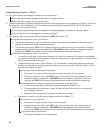
FIGURE 12-3. Three-wire RTD
Consult the table for resistance-temperature data. Lead resistance is about
0.05 ohm/ft at 25°C. Therefore, 15 feet of cable increases the resistance by
about 1.5 ohm. The resistance between the RTD return and RTD sense leads
should be less than 2 ohms.
Temperature Pt 100 Pt 1000 3K Balco
Resistance Resistance Resistance
0°C 100.0 ohms 1000 ohms 2670 ohms
10°C 103.9 ohms 1039 ohms 2802 ohms
20°C 107.8 ohms 1078 ohms 2934 ohms
25°C 109.6 ohms 1096 ohms 3000 ohms
30°C 111.7 ohms 1117 ohms 3067 ohms
40°C 115.5 ohms 1155 ohms 3198 ohms
50°C 119.4 ohms 1194 ohms 3330 ohms
60°C 123.2 ohms 1232 ohms 3472 ohms
70°C 127.1 ohms 1271 ohms 3594 ohms
80°C 130.9 ohms 1309 ohms 3726 ohms
90°C 134.7 ohms 1347 ohms 3858 ohms
100°C 138.5 ohms 1385 ohms 3990 ohms
TABLE 12-1. RTD Resistance Values