


MODEL 3081 pH/ORP SECTION 2.0
INSTALLATION
8
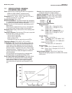
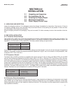
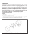
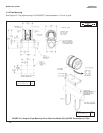
FIGURE 2-1. Model 3081 pH/ORP Transmitter - Exploded Drawing of Circuit Board Stack
2.2.4 Preamplifier Location
pH sensors produce a high impedance voltage signal that must be preamplified before use. The signal can be preampli-
fied before it reaches the transmitter or it can be preamplified in the transmitter. To work properly, the transmitter must know
where preamplification occurs. Although ORP sensors produce a low impedance signal, the voltage from an ORP sensor
is amplified the same way as a pH signal.
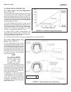
If the sensor is wired to the transmitter through a junction box, the preamplifier is ALWAYS in either the junction box or the
sensor. Junction boxes can be attached to the sensor or installed some distance away. If the junction box is not attached
to the sensor, it is called a remote junction box. In most junction boxes used with the Model 3081 pH/ORP, a flat, black
plastic box attached to the same circuit board as the terminal strips houses the preamplifier. The preamplifier housing in
the 381+ sensor is crescent shaped.
If the sensor is wired directly to the transmitter, the preamplifier can be in the sensor or in the transmitter. If the sensor
cable has a GREEN wire, the preamplifier is in the sensor. If there is no green wire, the sensor cable will contain a coax-
ial cable. A coaxial cable is an insulated wire surrounded by a braided metal shield. Depending on the sensor model, the
coaxial cable terminates in either a BNC connector or in a separate ORANGE wire and CLEAR shield.
2.2.5 Changing Switch and Jumper Positions
If the sensor and installation does not match the transmitter default settings in Section 2.2.1, change the settings to the
correct values.
1. Refer to Figure 2-1.
2. Loosen the cover lock nut until the tab disengages from the front cover. Unscrew the cover.
3. Remove the three bolts holding the circuit board stack.
4. Lift out the display board. Do not disconnect the ribbon cable between it and the CPU board. The CPU and analog
boards are joined by a pin and socket connector along the bottom edge of the boards. Carefully disengage the CPU
board from the analog board. The analog board will remain attached to the transmitter body.