


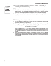
62
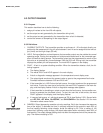
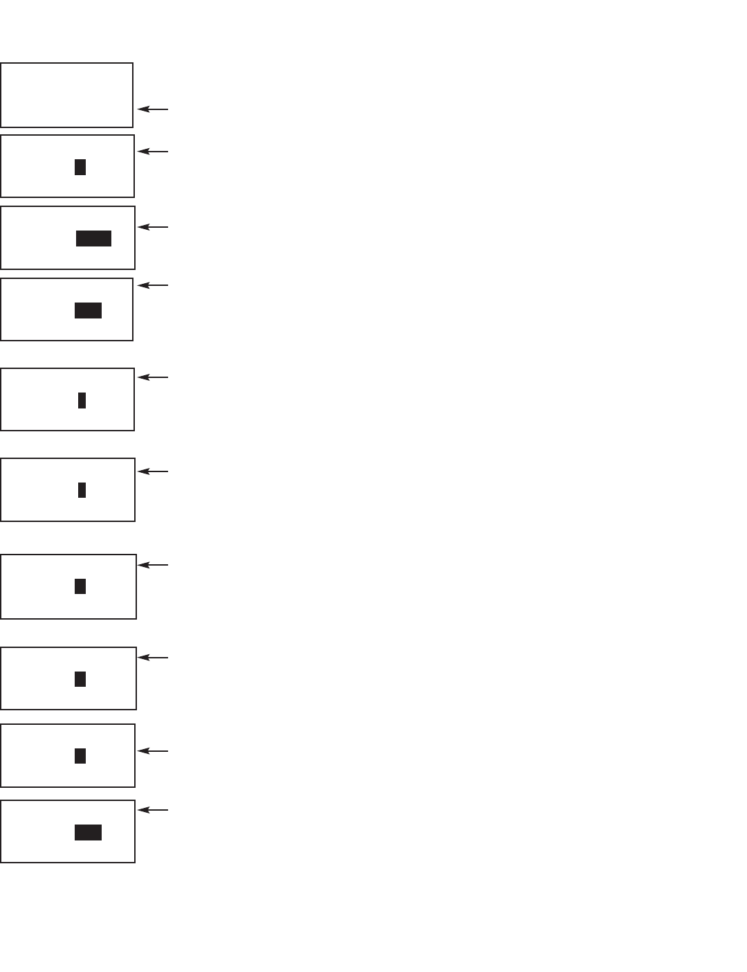
8.4.3 Procedure
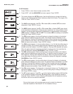
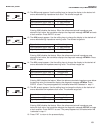
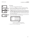
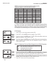
1. Press PROG on the infrared remote controller (IRC).
2. Press NEXT until the diAGnOStIC sub-menu appear. Press ENTER .
3. The screen displays the rOFFSt prompt. Use the editing keys to change the flashing
display to the desired standardization (reference) offset (in millivolts). The range is 0 to
1000 mV. Press ENTER to save.
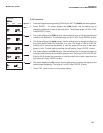
4. The dIAG prompt appears. Use Ï or
Ð
to enable (On) or disable (OFF) the sensor
diagnostics. Press ENTER to save.
5. The IMPtC prompt appears. Use Ï or
Ð
to enable (On) or disable (OFF) glass imped-
ance temperature compensation. Because glass impedance is a strong function of tem-
perature, correcting glass impedance for temperature is recommended. A third setting
(SPC) appears in addition to On and OFF. Do not select SPC; the setting is intended for
factory use. Press ENTER to save.
6. The GFH prompt appears. Use the editing keys to change the display to the desired
glass electrode impedance high fault value. The allowed values are between 0 and
2000 megohms. Entering 0000 disables the feature. When the glass electrode imped-
ance exceeds the fault value, the transmitter displays the diagnostic message GLASS-
FAIL and sets a fault condition. Press ENTER to save.
7. The GWH prompt appears. In the transmitter display, WJ is a W. Use the editing keys to
change the display to the desired glass electrode impedance high warning value. The
allowed values are between 0 and 2000 megohms. Entering 0000 disables the feature.
When the glass electrode impedance exceeds the warning value, the transmitter dis-
plays the diagnostic message GLASSWArn. Press ENTER to save.
8. The GWL prompt appears. Use the editing keys to change the display to the desired
glass electrode impedance low warning value. The allowed values are between 0 and
900 megohms. Entering 0000 disables the feature. When the glass electrode imped-
ance drops below the warning value, the transmitter displays the diagnostic message
GLASSWArn. Press ENTER to save.
9. The GFL prompt appears. Use the editing keys to change the display to the desired
glass electrode impedance low fault value. The allowed values are between 0 and 900
megohms. Entering 0000 disables the feature. When the glass electrode impedance
drops below the fault value, the transmitter displays the diagnostic message GLASS-
FAIL and sets a fault condition. Press ENTER to save.
10. The CAL prompt appears. This diagnostic is intended for factory use. The default value
000 should appear. If 000 is not showing, use the editing keys to change the display to
000. Press ENTER to save.
11. The rEF prompt appears. Press Ï or
Ð
until the desired setting appears. LO identifies
a low impedance reference electrode, and HI identifies a high impedance reference
electrode. Press ENTER to save. Selecting LO disables the low impedance warning
and failure limits for the reference electrode.
NOTE
Be sure the jumpers on the analog board are set to match the reference
electrode impedance. See Section 2.2, Pre-Installation Set Up.
MODEL 3081 pH/ORP SECTION 8.0
PROGRAMMING FOR pH MEASUREMENTS
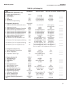
PROGRAM
IM PtC
EXIT NEXT ENTER
ON
PROGRAM
GFH
EXIT ENTER
1
500
PROGRAM
GWJH
EXIT ENTER
1 000
PROGRAM
GWJL
EXIT ENTER
0020
PROGRAM
GFL
EXIT ENTER
00 1 0
PROGRAM
rOFFSt
EXIT ENTER
PROGRAM
dIAGnOS TIC
EXIT NEXT ENTER
060
PROGRAM
d I A G
EXIT ENTER
OFF
PROGRAM
rEF
EXIT ENTER
LO
PROGRAM
CAL
EXIT ENTER
0
00