


104
MODEL 3081 pH/ORP SECTION 12.0
TROUBLESHOOTING
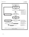
12.5.5 pH Reading in Buffer Drifts During Manual Calibration
A. Allow adequate time for the temperature of the sensor to reach the temperature of the buffer. If the sensor was in a
process substantially hotter or colder than the buffer, allow at least 20 minutes for readings in the buffer to stabilize.
Alternatively, place the sensor in a container of water at ambient temperature for 20 minutes before starting the
calibration.
B. Be sure to swirl sensor after placing it in each new buffer solution.
C. Finally, check the sensor. Verify that wiring is correct. Also, the sensor may be dirty or aged, or the reference junction
may be depleted.
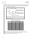
1. Check that the sensor is properly wired to the transmitter. See Section 3.0. Pay particular attention to terminals
TB-10 (mV in), TB-7 (reference), and TB-8 (solution ground).
2. See Section 11.3 for cleaning procedures.
3. If the sensor is not rebuildable, see Section 11.3.4 for a method of rejuvenating the reference junction.
4. If the sensor is rebuildable, replenish the reference electrolyte and replace the liquid junction.
5. Replace the sensor. A clean pH sensor should not drift in buffer.
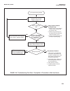
12.5.6 Sensor Does Not Respond To Known pH Changes
A. Verify that the change really happened. If pH response was being checked in buffers, recheck performance with fresh
buffers. If a process pH reading was not what was expected, check the performance of the sensor in buffers. Also,
use a second pH meter to verify that the expected change in the process pH really occurred.
B. Check the sensor. Verify that wiring is correct. Also, the sensor may be dirty or aged, or the reference junction may be
depleted.
1. Check that the sensor is properly wired to the transmitter. See Section 3.0. Pay particular attention to terminals
TB-10 (mV in), TB-7 (reference), and TB-8 (solution ground).
2. See Section 11.3 for cleaning procedures.
C. If a clean, properly wired sensor does not respond to pH changes, the glass bulb is probably broken or cracked.
If a spare sensor is available, check the spare.
If the spare sensor responds to pH changes, the old sensor has failed.
If the spare sensor does not respond to pH changes, go to step D.
If a spare sensor is not available, check the glass impedance (GIMP) of the existing sensor. See Section 12.7.
If the impedance is less than about 20 megohm, the pH glass is cracked. Replace the sensor.
If the impedance is greater than about 20 megohm, go to step D.
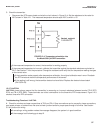
D. Check transmitter performance by simulating pH inputs. See Section 12.8.
If the transmitter responds to simulated inputs, the problem must lie with the sensor or the interconnecting wiring.
Verify the interconnecting wiring point to point. Fix or replace bad cable. If cable is good, replace the pH sensor.
If the transmitter does not respond to simulated inputs, replace the board stack (PN 23574-02).
12.5.7 Buffer Calibration Is Acceptable; Process pH is Slightly Different from Expected Value.
Differences between pH readings made with an on-line instrument and a laboratory or portable instrument are normal.
The on-line instrument is subject to process variables, for example grounding potentials, stray voltages, and orientation
effects, that do not affect the laboratory or portable instrument. To make the Model 3081 pH/ORP transmitter match the
reading from a second pH meter refer to Section 7.7.