


10
MODEL 3081 pH/ORP SECTION 2.0
INSTALLATION
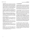
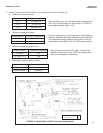
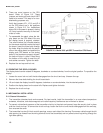
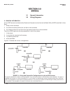
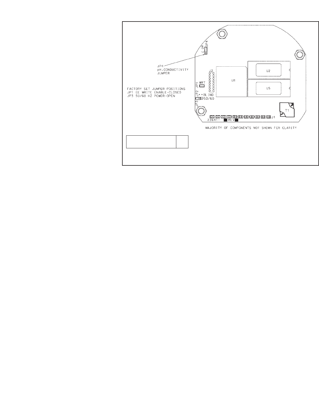
6. There are more jumpers on the CPU
board. Refer to Figure 2-3. These
jumpers are factory set and should NOT
need to be moved. This step is for trou-
bleshooting purposes only.
Verify that jumpers JP-1, JP-3, and JP-4
on the CPU board are in the positions
shown in Figure 2-3. For installations
where 50 Hz ac power is present, closing
JP-3 may improve immunity of the trans-
mitter to noise.
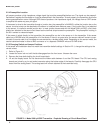
7. To reassemble the stack, place the dis-
play board on the CPU board. Be sure
the display board is properly oriented.
The small window (the infrared detector
for the remote controller) marks the top of
the board. Insert the three bolts through
the holes. Align the bolts with the stand-
offs on the analog board and position the
display and CPU boards on the analog
board. If the boards are properly aligned,
the bolts will drop in place. Press along
the bottom of the stack to seat the pin
and socket connector. Tighten the bolts.
8. Replace the end cap and lock nut.
2.3 ORIENTING THE DISPLAY BOARD
The display board can be rotated 90 degrees, clockwise or counterclockwise, from the original position. To reposition the
display:
1. Loosen the cover lock nut until the tab disengages from the circuit end cap. Unscrew the cap.
2. Remove the three bolts holding the circuit board stack.
3. Lift and rotate the display board 90 degrees, clockwise or counterclockwise, into the desired position.
4. Position the display board on the stand offs. Replace and tighten the bolts.
5. Replace the circuit end cap.
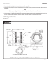
2.4 MECHANICAL INSTALLATION
2.4.1 General information
1. The transmitter tolerates harsh environments. For best results, install the transmitter in an area where temperature
extremes, vibrations, and electromagnetic and radio frequency interference are minimized or absent.
2. To prevent unintentional exposure of the transmitter circuitry to the plant environment, keep the security lock in place
over the circuit end cap. To remove the circuit end cap, loosen the lock nut until the tab disengages from the end cap,
then unscrew the cover.
3. The transmitter has two 3/4-inch conduit openings, one on each side of the housing. Run sensor cable through the left
side opening (as viewed from the wiring terminal end of the transmitter) and run power/current loop wiring through the
right side opening.
FIGURE 2-3. Model 3081 pH/ORP Transmitter CPU Board
DWG. NO. REV.
40008125 A