


98
MODEL 3081 pH/ORP SECTION 12.0
TROUBLESHOOTING
B. The RTD sense or the RTD return wire inside the sensor cable may be broken. Keep the sensor wires attached and
jumper TB-3 and TB-4.
If the diagnostic message disappears, either the RTD return or RTD sense wire is broken. To verify a broken wire,
disconnect the leads and measure the resistance between them. Installing the jumper completes the circuit, but
bypasses the three-wire function. The transmitter no longer corrects for changes in lead wire resistance with
temperature. Replace the sensor as soon as possible.
If the diagnostic message remains, go to step C.
C. The cable connecting the sensor to the transmitter may be too long. Test using a sensor with a shorter cable.
If shortening the cable eliminates the problem, move the transmitter closer to the sensor. It may also be possible
to increase diameter of the RTD wires. Consult the factory for assistance.
If the diagnostic message remains go to step D.
D. Check the performance of the transmitter. Simulate both temperature and pH. See Section 12.4.6 (steps B and C) for
temperature simulation and Section 12.8 for pH simulation.
If the transmitter fails either simulation, the electronic board stack (PN 23574-02) should be replaced.
If the transmitter passes the simulations, the transmitter is in good condition and the sensor should be replaced.
12.4.8 InPUt WArn
InPUt WArn means that the input value or the calculated pH is outside the measurement range. The measured pH is less
than -2 or greater than 16.
Troubleshooting Flowchart-InPUt WArn
A. Check for miswires and open connections, particularly at TB-10. Open connections can be caused by loose
connections, poor spade crimps, or broken wires. Be sure to check junction boxes for proper pass through of all
wires. See Section 3.0 for junction box wiring.
If correcting a wiring problem clears the message, the system is in good condition.
If the message is still showing go to step B.
B. Check that the transmitter is working properly by simulating a pH input. See Section 12.8.
If the transmitter does not respond to simulated inputs, replace the board stack (PN 23574-02).
If the transmitter performs satisfactorily and the preamplifier is located in a remote junction box or in a sensor -
mounted junction box, go to step C.
If the transmitter performs properly and the preamplifier is located in the transmitter, the sensor has failed and
should be replaced.
C. The problem may lie with the remote preamplifier or with the cable connecting the preamplifier and junction box to the
transmitter.
1. Be sure all wires between the junction box and the transmitter are connected.
2. Use Rosemount Analytical cable. Generic cable may not work. Refer to Section 3.0 for part numbers.
If the diagnostic message clears, the interconnecting cable was the problem.
If the message remains, go to step D.
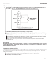
D. Confirm that the problem is with the remote preamplifier. Wire the pH sensor directly to the transmitter. Move switch
S-1 to the "transmitter" position for the test and return it to the "sensor or j-box" position afterwards. See Section 2.2.
If the error message clears, the remote preamplifier is faulty. Replace the preamplifier.
If the error message remains, the sensor has failed. Replace the sensor.